Door hardware drive mechanism with sensor

a technology of drive mechanism and door hardware, which is applied in the direction of mechanical controls, wing accessories, mechanical apparatuses, etc., can solve the problem of changing the location of this limit, and achieve the effect of reducing the noise produced

Active Publication Date: 2011-03-03
SARGENT MANUFACTURING CO INC
View PDF95 Cites 48 Cited by
  • Summary
  • Abstract
  • Description
  • Claims
  • Application Information

AI Technical Summary

Benefits of technology

[0042]However, this design may cause an audible noise as the door hardware component is released. Noise made during door hardware operation is objectionable in high quality door hardware. To prevent the hardware from making this noise, the preferred design uses the controller to actively drive the door hardware component in reverse—away from the second position towards the first position with a residue of remaining power.
[0043]The residue of remaining power is typically found in filter capacitors for the power supply of the driver. The controller removes power and uses the remaining stored residue of power to provide a controlled motion away from the second position towards the first position. Typically, there is insufficient power remaining for the driver to completely return the door hardware component to the first position under power. The final part of the return motion, after the stored residue of power has been depleted, is provided by the biasing spring. Nonetheless, this controlled or “soft” release action greatly reduces the noise produced at the initial release when the biasing spring for the door hardware component and the spring connecting the driver to the component are maximally compressed.

Problems solved by technology

The location of this limit may change in different installations, over time due to wear or in different products using the same drive mechanism.

Method used


Image

  • Door hardware drive mechanism with sensor
  • Door hardware drive mechanism with sensor
  • Door hardware drive mechanism with sensor

Examples


Embodiment Construction

)

[0057]In describing the preferred embodiment of the present invention, reference will be made herein to FIGS. 1-10 of the drawings in which like numerals refer to like features of the invention.

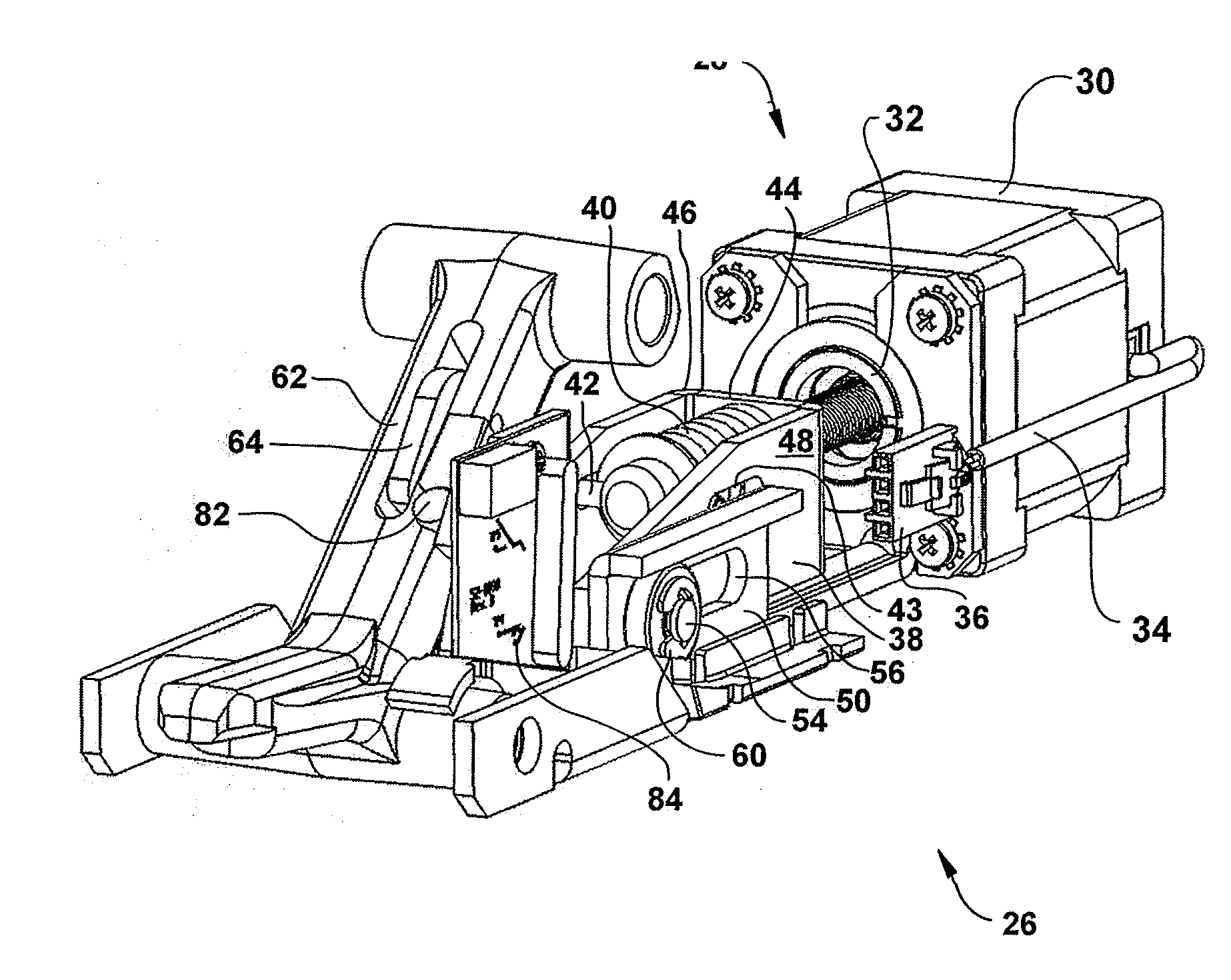
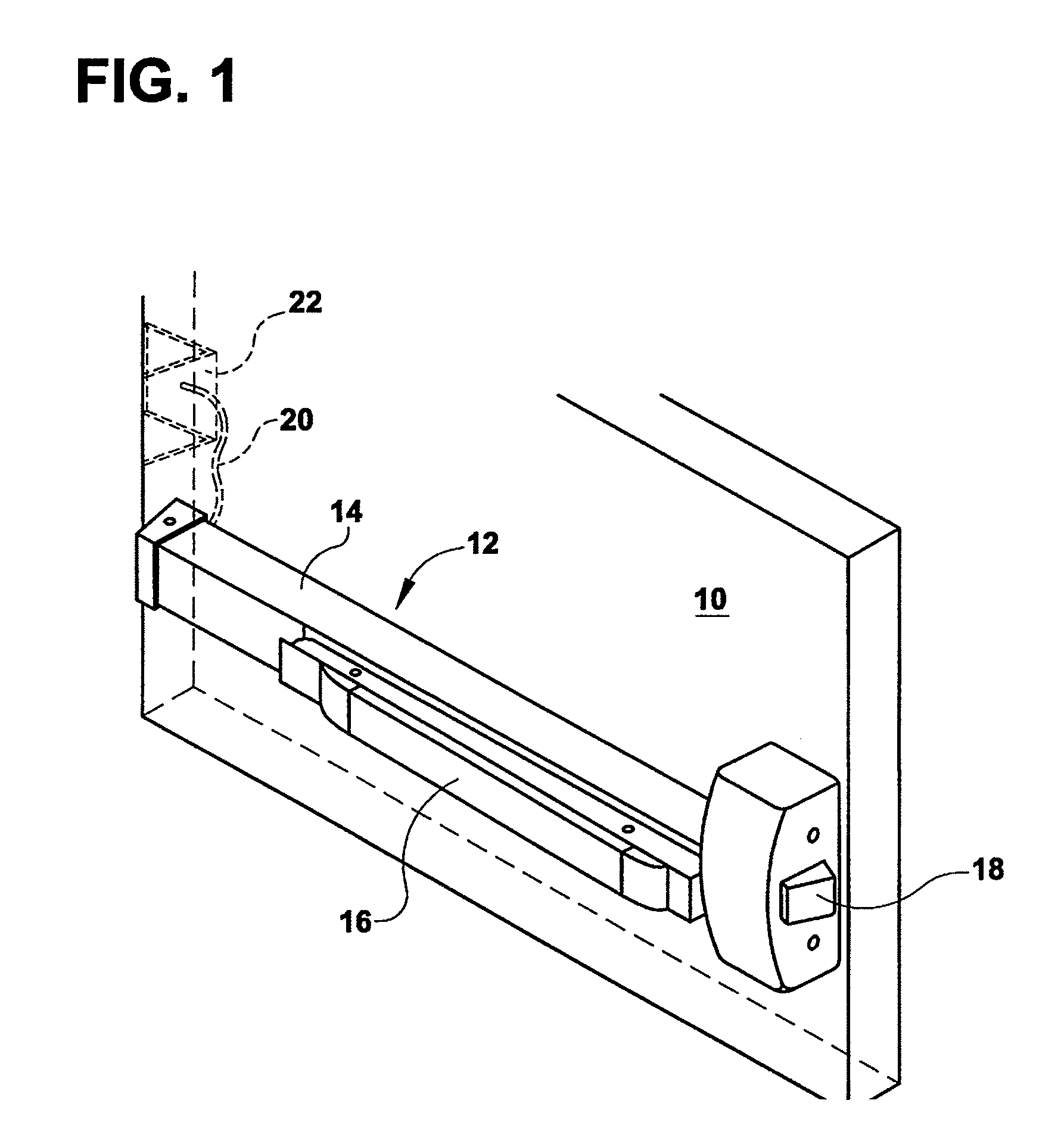
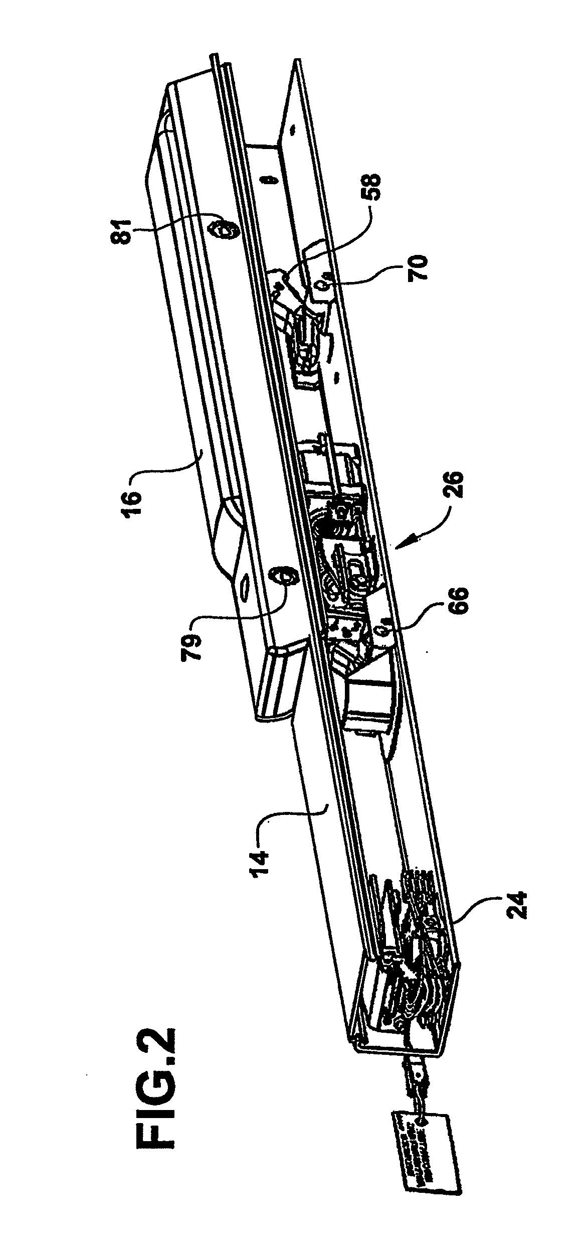
[0058]Referring to FIG. 1, a door 10 is provided with a pushbar exit device 12 having a body 14, a pushbar 16 and a latchbolt 18. Referring to FIG. 2, a drive mechanism according to the invention is located within the body 14 of the exit device and is electrically connected to power and a control system with wire 20 through electric door hinge 22. The drive mechanism includes a controller 24 and a drive mechanism assembly 26.

[0059]The controller is preferably a microcontroller with integrated inputs, outputs, memory and a central processing unit, although other conventional control systems may be used. The controller unit is also provided with power connections and electronic controls for a linear actuator 28 found in the drive mechanism assembly 26. In the preferred design, the electronics ...


PUM


Abstract

A drive mechanism for door hardware, such as a pushbar exit device, includes a driver for moving a component of the door hardware, a controller for controlling the operation of the driver, a sensor for detecting motion of the moving component and a spring connected between the driver and the door hardware component. The spring allows the driver to move for a period of time after the component has stopped moving. The controller monitors the sensor and moves the component until the sensor indicates that the driven component has stopped moving. The sensor produces an output signal and the controller detects an inflection point in the output signal when the component stops moving while the driver is still operating.

Description

BACKGROUND OF THE INVENTION[0001]1. Field of the Invention[0002]This invention relates to drive mechanisms for door hardware, such as drive mechanisms for retracting the pushbar of an exit device or remotely locking a door lock. More specifically, the present invention relates to drive mechanisms that include a sensor for detecting motion of the door hardware component being driven.[0003]2. Description of Related Art[0004]Door hardware, such as exit devices, mortise locks and bored locks, typically include one or more elements that move between two positions, such as a retracted position and an extended position. For example, a pushbar exit device includes a pushbar that moves inward to retract a latchbolt from a strike in a doorframe and outward to extend the latchbolt. Lock mechanisms include a handle, a latchbolt and other locking elements that may be driven between two alternative positions. The moving lock component may be a locking element that locks and unlocks the door or it...

Claims


Application Information

Patent Timeline
Patent Type & Authority Applications(United States)
IPC IPC(8): E05F15/20E05F15/60
CPCE05B47/0012E05B65/1053E05B2047/0023E05B65/1093E05B17/22E05B65/108E05B2047/0031E05B2047/0067Y10T292/0908E05B53/00E05B47/00
Inventor LOWDER, SCOTT B.MARTIN, DALE D.HULSE, JONHUNT, ROBERT C.LIMONCELLI, ARTHURWONG, WAI P.
Owner SARGENT MANUFACTURING CO INC
Why Eureka
Try Eureka