Damper for input shaft of transmission

Active Publication Date: 2014-02-13
HYUNDAI MOTOR CO LTD
View PDF1 Cites 4 Cited by
  • Summary
  • Abstract
  • Description
  • Claims
  • Application Information

AI Technical Summary

Benefits of technology

The present invention provides a damper for the input shaft of a transmission that reduces rider noise and vibration. This is achieved by applying inertial force to the input shaft, which stops a resonance from occurring in a specific frequency band. The invention solves the issue of limited space for installation and ensures that the transmission can be easily installed in vehicles without increasing the length.

Problems solved by technology

This technique is therefore not easily applied to the existing transmission housing or requires an increase in the length of the transmission, thus complicating the installation of the transmission in a vehicle.

Method used


Image

  • Damper for input shaft of transmission
  • Damper for input shaft of transmission
  • Damper for input shaft of transmission

Examples


Embodiment Construction

[0023]Reference will now be made in detail to various embodiments of the present invention(s), examples of which are illustrated in the accompanying drawings and described below. While the invention(s) will be described in conjunction with exemplary embodiments, it will be understood that the present description is not intended to limit the invention(s) to those exemplary embodiments. On the contrary, the invention(s) is / are intended to cover not only the exemplary embodiments, but also various alternatives, modifications, equivalents and other embodiments, which may be included within the spirit and scope of the invention as defined by the appended claims.

[0024]Hereinafter, a damper for an input shaft of a transmission according to an exemplary embodiment of the present invention will be described in detail with reference to the attached drawings.

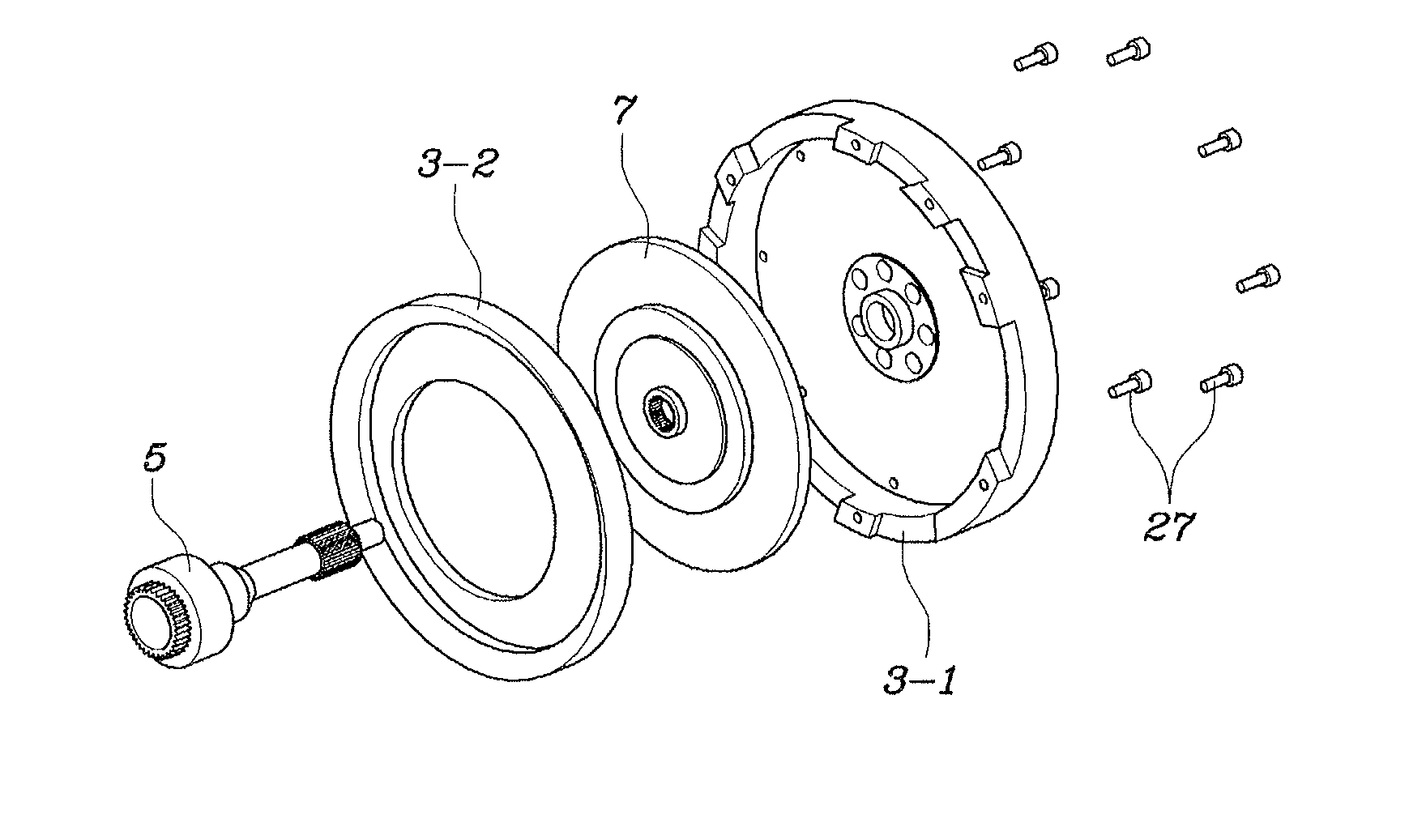
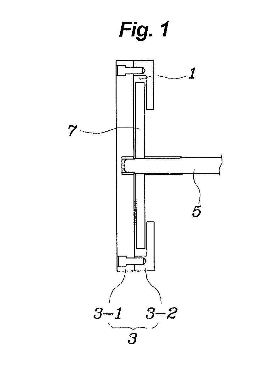
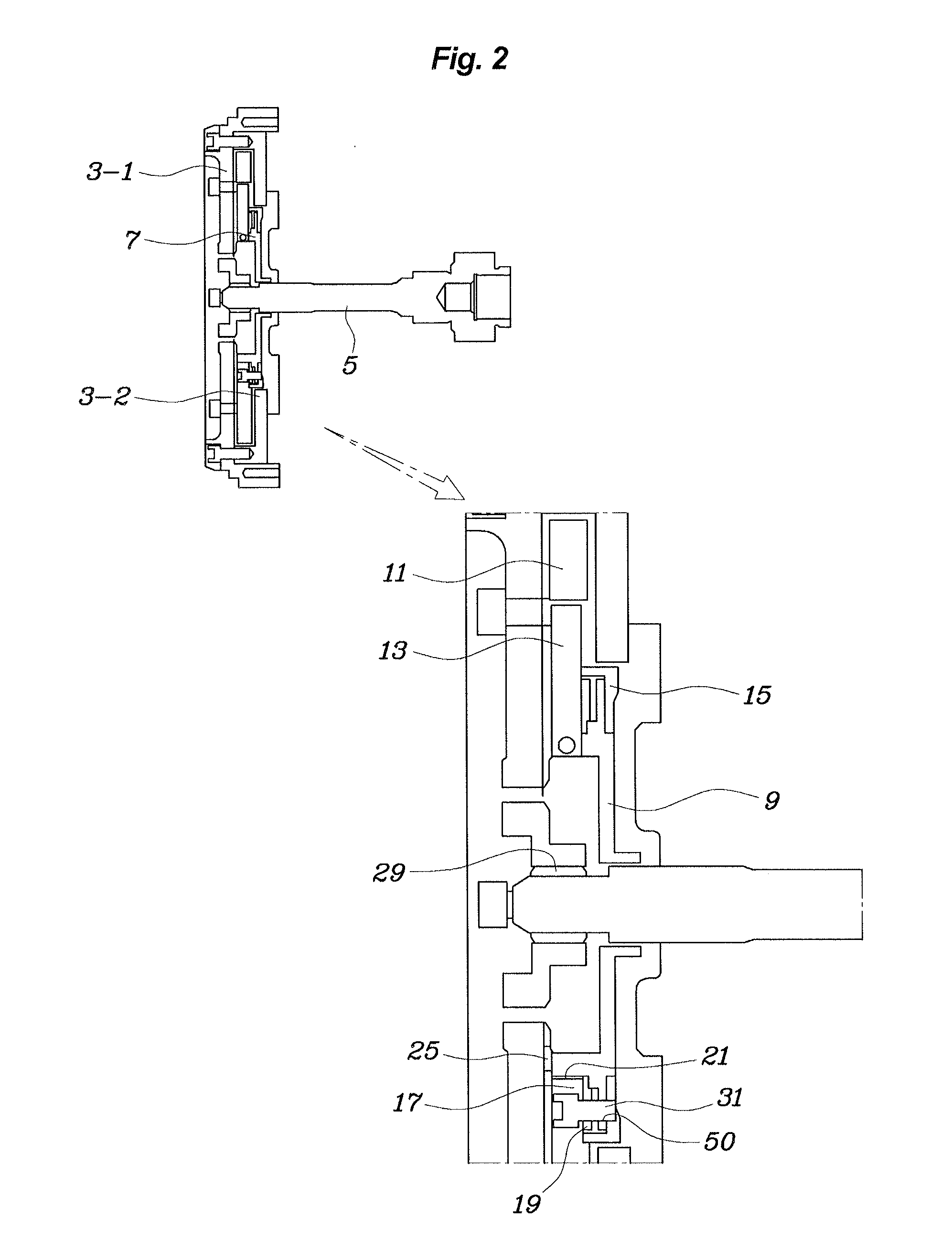
[0025]Referring to FIGS. 1 through 4, the damper according to an exemplary embodiment of the present invention includes a flywheel 3, an ...


PUM


Abstract

A damper apparatus for an input shaft of a transmission, may include a flywheel having a reception space in which a inertial body may be provided so as to be rotatable relative to the flywheel, the input shaft extending into the reception space of the flywheel, and an inertial body assembly slidably coupled to the input shaft so as to provide rotational inertial force to the input shaft, the inertial body assembly being disposed in the reception space.

Description

CROSS-REFERENCE TO RELATED APPLICATION[0001]The present application claims priority to Korean Patent Application No. 10-2012-0087321, filed on Aug. 9, 2012, the entire contents of which is incorporated herein for all purposes by this reference.BACKGROUND OF THE INVENTION[0002]1. Field of the Invention[0003]The present invention relates generally to a damper which is provided on an input shaft of a transmission to mitigate rattle noise of the transmission and, more particularly, to a technique which applies inertial force to the input shaft of the transmission and stops resonance from occurring in a specific frequency band, thus mitigating rattle noise of the transmission.[0004]2. Description of Related Art[0005]Conventionally, an inertial plate is provided on an input shaft of a transmission so that resonance of a specific frequency band which causes a problem of rattle noise of the transmission can be effectively avoided even when a DMF (Dual Mass Flywheel) or the like is not used....

Claims


Application Information

Patent Timeline
IPC IPC(8): F16F15/26
CPCF16F15/26F16H57/0006F16F15/1428Y10T74/2121Y10T74/213Y10T74/2131F16F15/30F16H57/021F16H57/023
Inventor HWANG, JAE WOONGJIN, YONG WOOKOH, WAN SOOSHIN, SEOK YOUNGPARK, DONG HOON
Owner HYUNDAI MOTOR CO LTD
Why Eureka
Try Eureka