
Microsphere plasma display

a plasma display and microsphere technology, applied in the direction of gas-filled discharge tubes, electric discharge tubes, electrical apparatus, etc., can solve the problems of shortening the life of phosphor and pdp, and achieve the effect of simple alignment methods

Inactive Publication Date: 2008-11-25
IMAGING SYST TECH
View PDF12 Cites 57 Cited by
  • Summary
  • Abstract
  • Description
  • Claims
  • Application Information

AI Technical Summary

Benefits of technology

[0028]The practice of this invention also allows for encapsulated pixel plasma display devices to be produced with simple alignment methods using non-rigid materials such as plastic.
[0030]The practice of this invention allows for a low cost continuous roll manufacturing process by separating the production of light producing encapsulated pixel elements from the production of the substrate.
[0031]The practice of this invention allows for effective electrical contact between electrodes and the microspheres of the encapsulated pixel device.
[0032]The practice of this invention allows for visual inspection and rework of the interconnect between the microspheres and the electrodes.
[0033]The practice of this invention allows for the addressing of multiple rows simultaneously without splitting the screen as is done with conventional plasma displays.
[0034]The practice of this invention allows for reduction of false contour as is often observed in a standard plasma display.

Problems solved by technology

The discharge between the two opposite electrodes generates electrons and ions that bombard and deteriorate the phosphor thereby shortening the life of the phosphor and the PDP.

Method used


Image

  • Microsphere plasma display
  • Microsphere plasma display
  • Microsphere plasma display

Examples


Embodiment Construction

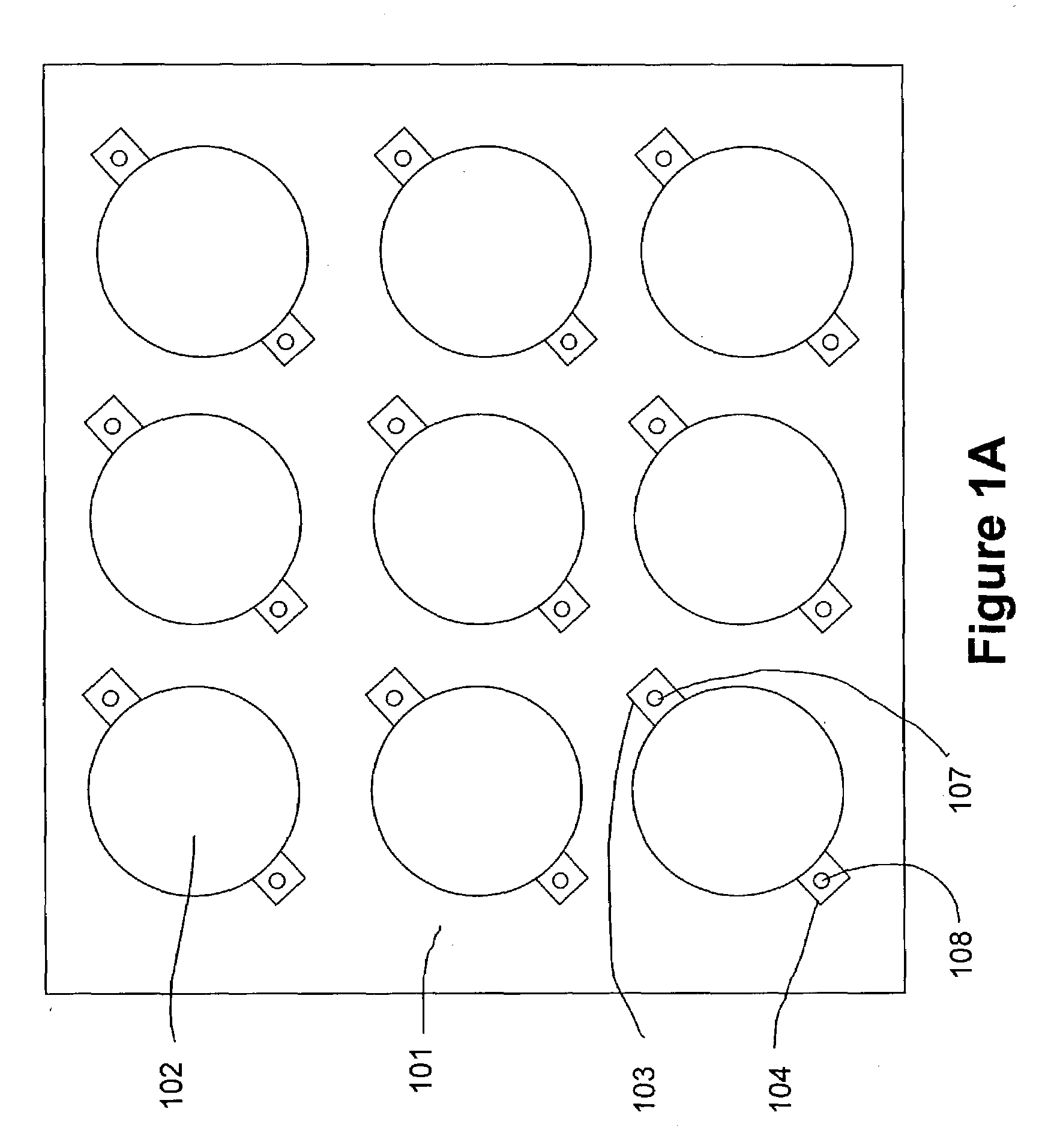
[0049]FIGS. 1A, 1B, 1C, and 1D show one preferred cell configuration for a plasma display device using a single flexible substrate and gas encapsulated microspheres, each in contact with two electrodes. FIG. 1A, shows the front viewing side of a substrate 101. The microsphere 102 is in contact with surface electrode pads or traces 103 and 104 which reside on substrate 101.

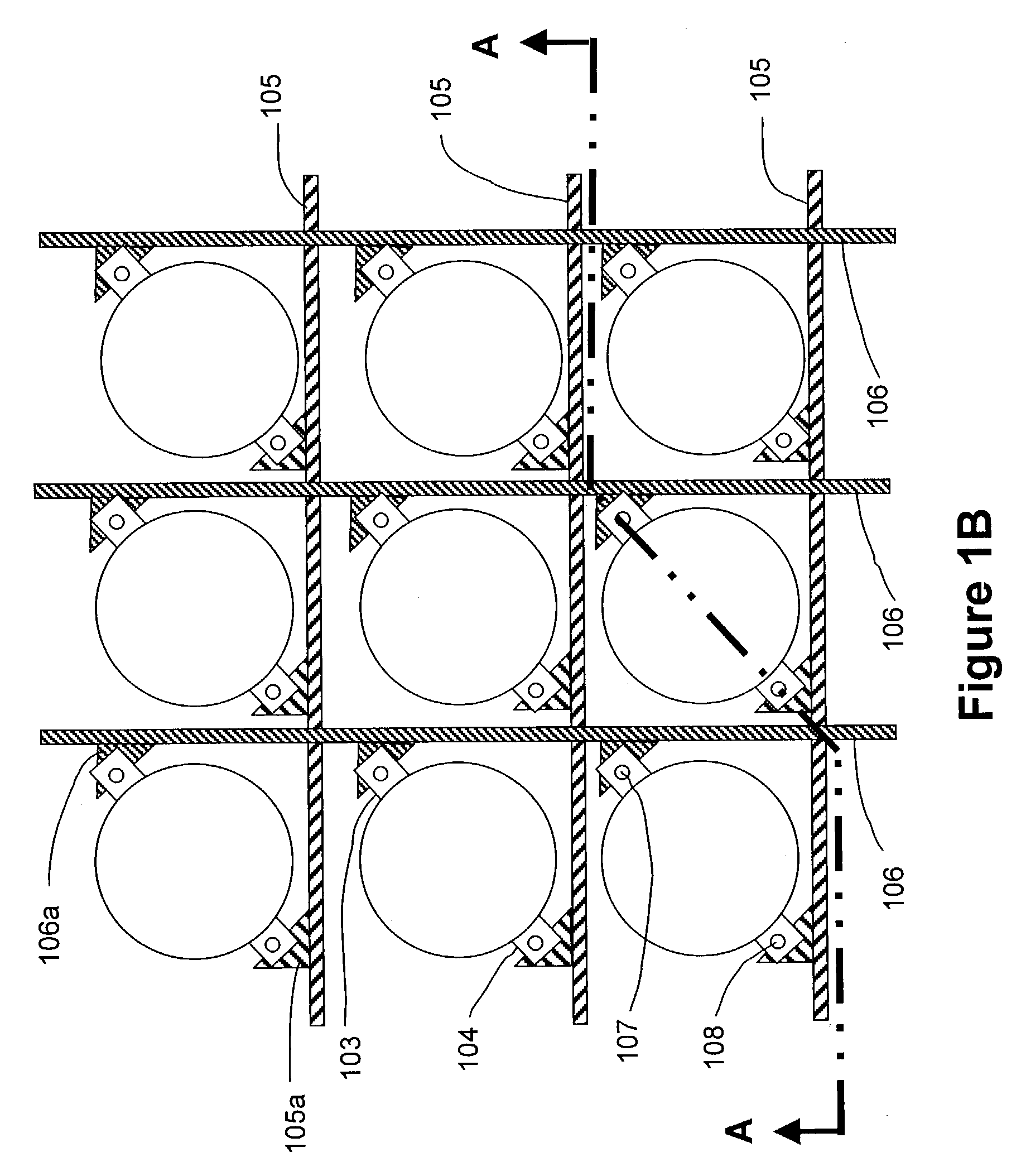
[0050]FIG. 1B shows a cross section of the electrode layers of the substrate 101 with reference to the microsphere 102. Row electrodes 105 and column electrodes 106 are on different internal layers. The row and column electrodes are orthogonal to one another and form an addressable matrix. Bridge conductor 105a is an extension of row electrode 105 to via 108. Bridge conductor 106a is an extension of column electrode 106 to via 107.

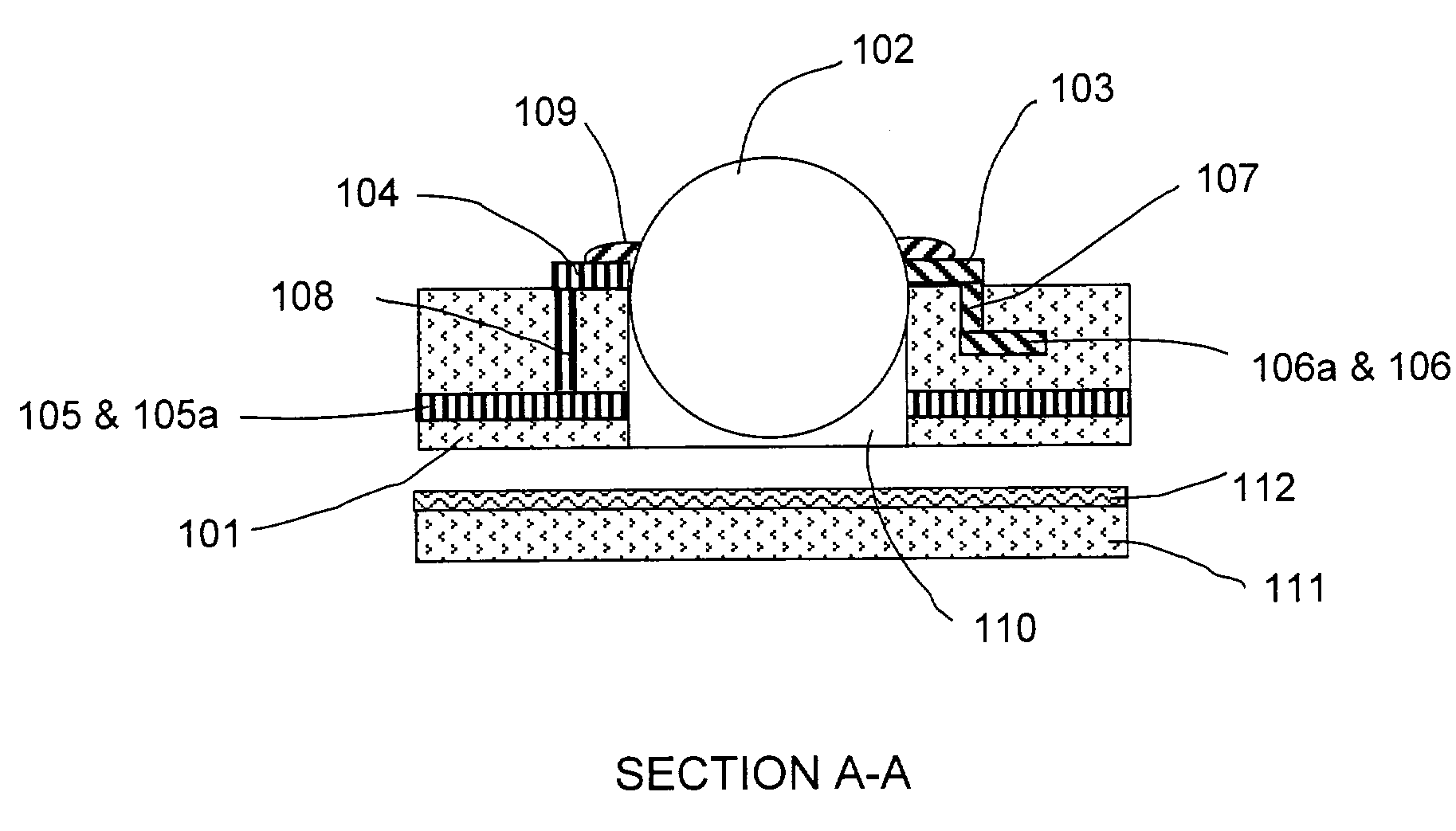
[0051]FIG. 1C is a sectional view of a single microsphere cell or pixel of the display. The microspheres 102 are seated in wells 110 formed in the substrate 101 at each cell site. The sec...


PUM


Abstract

A monolithic or single substrate AC gas discharge (plasma) display constructed of gas filled microspheres positioned on a substrate in electrical contact with two or more electrode.

Description

RELATED PATENT APPLICATION[0001]This application claims priority under 35 USC 119(e) of Provisional Patent Application 60 / 381,822 filed May 21, 2002.FIELD OF THE INVENTION[0002]This invention relates to a gas discharge (plasma) structure wherein an ionizable gas is confined within an enclosure and is subjected to sufficient voltage(s) to cause the gas to discharge. This invention particularly relates to a single substrate gas discharge plasma display panel (PDP) and the use of microspheres to encapsulate the cell structure and simplify the method of production. This invention is particularly suitable for producing flexible or bendable displays. When used in a PDP, a microsphere is called a Plasma-Sphere which is a trademark of the assignee of this patent application.BACKGROUND[0003]In a gas discharge plasma display, a single addressable picture element is a cell, sometimes referred to as a pixel. The cell element is defined by two or more electrodes positioned in such a way so as to...

Claims


Application Information

Patent Timeline
IPC IPC(8): H01J17/49
CPCH01J11/18
Inventor WEDDING, CAROL ANN
Owner IMAGING SYST TECH
Features
  • Generate Ideas
  • Intellectual Property
  • Life Sciences
  • Materials
  • Tech Scout
  • Unparalleled Data Quality
  • Higher Quality Content
  • 60% Fewer Hallucinations
Learn More