Internal pressure explosion-proof system

a technology of explosion-proof system and internal pressure, which is applied in frequency-division multiplex, fire alarms, instruments, etc., can solve the problems of automatic decrease of pressure in the internal pressure explosion-proof mechanism, user inability to recognize abnormalities, and unnecessary release of inactive gas/air

Inactive Publication Date: 2008-11-25
YASKAWA DENKI KK
View PDF9 Cites 10 Cited by
  • Summary
  • Abstract
  • Description
  • Claims
  • Application Information

AI Technical Summary

Benefits of technology

[0012]The preferred embodiments of the present invention have been developed in view of the above-mentioned and / or other problems in the related art. The preferred embodiments of the present invention can significantly improve upon existing methods and / or apparatuses.
[0015]With this internal pressure explosion-proof system, for example, high-pressure abnormality of the internal pressure explosion-proof mechanism can be detected, and the high-pressure abnormality can be notified to a user. Furthermore, excessive internal pressure can be reduced by releasing the inactive-gas / air. This allows immediate recognition of the abnormality by the user, and results in a quick check of the inactive-gas / air apparatus, etc. Moreover, the inactive-gas / air apparatus and / or the internal pressure explosion-proof mechanism can be prevented from being damaged by high pressure. Accordingly, stable operation of the internal pressure explosion-proof system can be realized.

Problems solved by technology

Furthermore, the pressure in the internal pressure explosion-proof mechanism is decreased automatically, and since no means for notifying it of a user, the user cannot recognize the abnormality.
In other words, no means for urging the maintenance and / or repair check was available, causing unnecessary releasing of the inactive-gas / air, which in turn becomes loads to the supplying source (e.g., compressor) of the inactive-gas / air.

Method used


Image

  • Internal pressure explosion-proof system
  • Internal pressure explosion-proof system
  • Internal pressure explosion-proof system

Examples


second embodiment

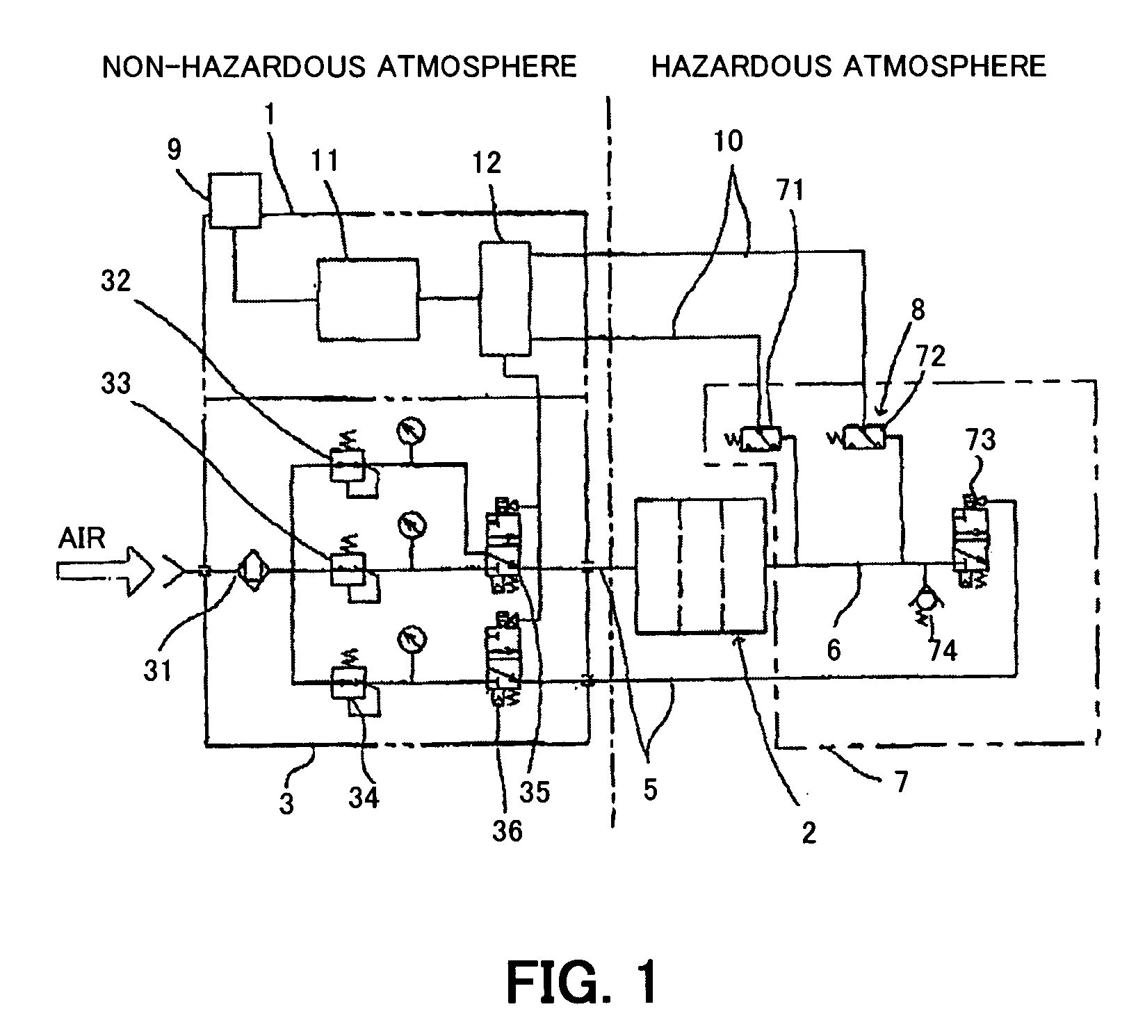
[0054]FIG. 4 is a block diagram showing the structure of the present invention. In FIG. 4, the same reference numerals are allotted to elements corresponding to the elements shown in FIG. 1. In this embodiment, instead of the pressure detector 72 shown in FIG. 1, a flow detector 721 is disposed at the downstream side of the pressure regulating valve 74. When the pressure of the inactive-gas / air flowing through the inactive-gas / air piping 6 becomes higher than the set pressure, the pressure regulating valve 74 is opened and the flow detector 721 detects the inactive-gas / air flowing through the pressure regulating valve 74. The flow detector 721 sends a signal to the control apparatus 1 when the detected flow rate exceeds a preset value. The flow detector 721 is set such that it can detect a small flow rate.

[0055]FIG. 5 is similar to the operation shown in FIG. 3. However, in FIG. 5, the mode shifts to a warning mode when the flow detector 721 detects the flow rate exceeding the prese...

third embodiment

[0056]FIG. 6 is a block diagram showing the structure of the present invention. In FIG. 6, the same reference numerals are allotted to elements corresponding to the elements shown in FIG. 1. In this embodiment, in place of the pressure detector 72 shown in FIG. 1, the pressure regulating valve 722 with a switch is used. This pressure regulating valve 722 with a switch is opened when the pressure of the inactive-gas / air flowing through the inactive-gas / air piping 6 becomes higher than a set pressure, and the valve 722 releases the inactive-gas / air to the atmosphere. The switch simultaneously sends a signal to the control apparatus 1. The working pressure of the pressure regulating valve 722 with a switch is set to be slightly higher than a normal pressure.

[0057]FIG. 7 is similar to the operation shown in FIG. 5. However, in FIG. 7, the mode shifts to a warning mode when the pressure regulating valve 722 with a switch is operated.

[0058]In each of the above embodiments, when a signal o...


PUM


Abstract

An internal pressure explosion-proof system is provided that is capable of detecting high-pressure abnormality of an internal pressure explosion-proof mechanism, urging a check of gas / air apparatus by providing a means for notifying a user of abnormality, and decreasing excessive pressure of an internal pressure chamber. A high-pressure abnormality detector and a pressure regulating valve are provided in an air discharging portion for releasing the gas / air discharged from the internal pressure explosion-proof mechanism. The working pressure of the high-pressure abnormality detector is set to be lower than the working pressure of the pressure regulating valve. The high-pressure abnormality detector sends a signal when the pressure becomes higher than the set pressure to make the alarm give a warning and makes the open valves open to decrease the pressure of the internal pressure chamber of the internal pressure explosion-proof mechanism which became excessive.

Description

[0001]This application claims priority under 35 U.S.C. §119 to Japanese Patent Application No. 2005-121821 filed on Apr. 20, 2005, the entire disclosure of which is incorporated herein by reference in its entirety.BACKGROUND OF THE INVENTION[0002]1. Field of the Invention[0003]The present invention relates to an internal pressure explosion-proof system, and some preferred embodiments relate to an internal pressure explosion-proof system preferably used as a robot system capable of detecting internal high pressure abnormality.[0004]2. Description of Related Art[0005]The following description sets forth the inventor's knowledge of related art and problems therein and should not be construed as an admission of knowledge in the prior art.[0006]An internal pressure explosion-proof system equipped with an inactive-gas / air supplying portion and an inactive-gas / air discharging portion is known. See for example, Japanese Patent No. 2796482 (hereinafter referred to as “Patent Document 1”). Ac...

Claims


Application Information

Patent Timeline
Patent Type & Authority Patents(United States)
IPC IPC(8): G08B21/00
CPCH01H35/24
Inventor KITAGAWA, TERUHISATAKAHASHI, SHINGI
Owner YASKAWA DENKI KK
Why Eureka
Try Eureka