Exposure apparatus and device manufacturing method

a technology of equipment and manufacturing method, applied in the field of equipment, can solve the problems of spreading damage, adverse effects on the accuracy of exposure measurement, etc., and achieve the effect of maintaining accuracy and accuracy of exposure measuremen

Inactive Publication Date: 2008-11-25
NIKON CORP
View PDF92 Cites 64 Cited by
  • Summary
  • Abstract
  • Description
  • Claims
  • Application Information

AI Technical Summary

Benefits of technology

[0010]In accordance with the present invention, since the damage due to the liquid having leaked out can be prevented from spreading, the exposure accuracy and the measurement accuracy can be maintained.

Problems solved by technology

When the liquid leaks out, the environment (humidity etc.) in which the exposure apparatus is placed changes due to the liquid having leaked out, and thus there occurs a possibility that the exposure accuracy and the measurement accuracy are adversely affected.
Further, if the liquid having leaked out is left as it is, various devices constituting the exposure apparatus may, for example, break down or rust, spreading the damage.

Method used


Image

  • Exposure apparatus and device manufacturing method
  • Exposure apparatus and device manufacturing method
  • Exposure apparatus and device manufacturing method

Examples


first embodiment

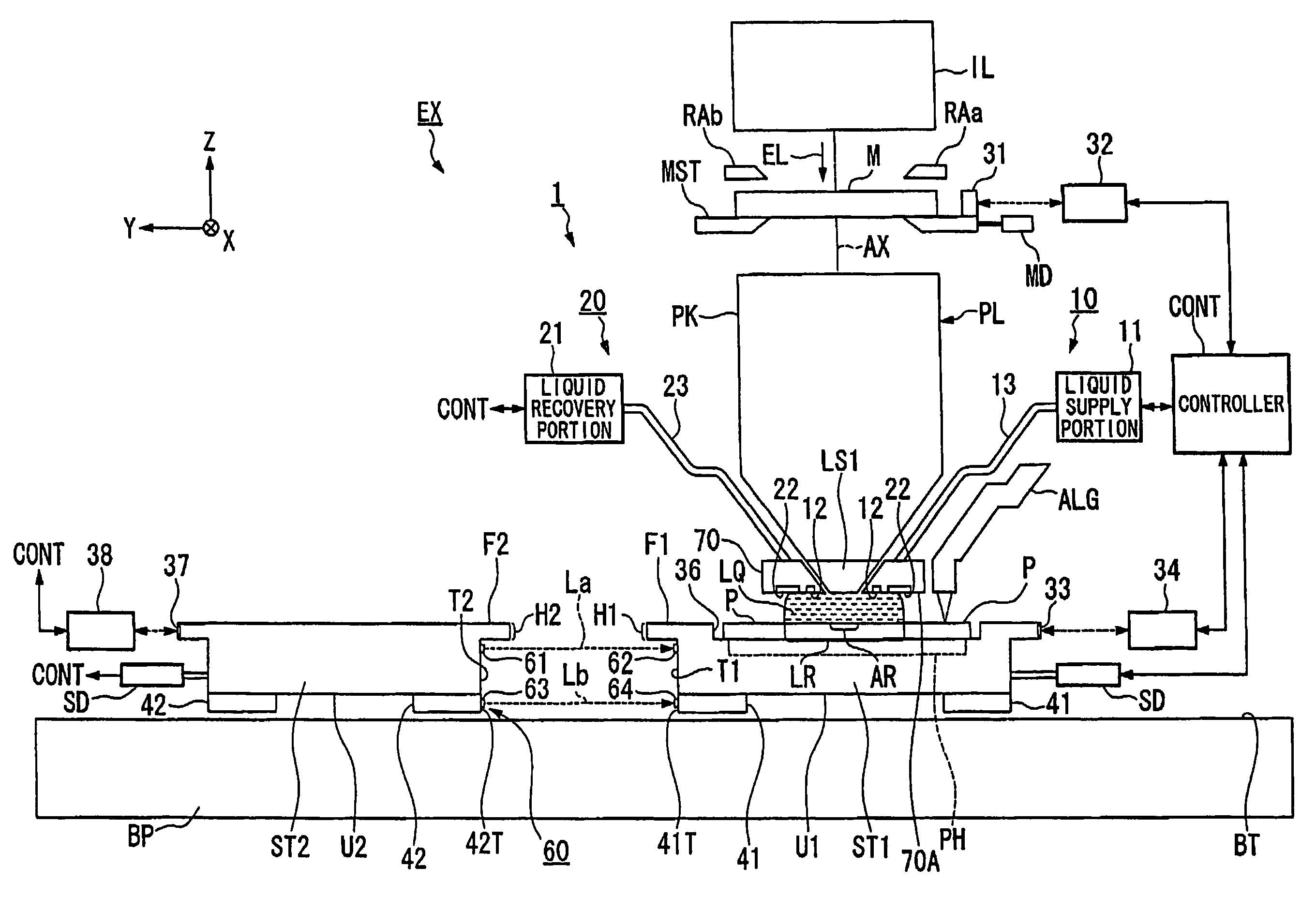
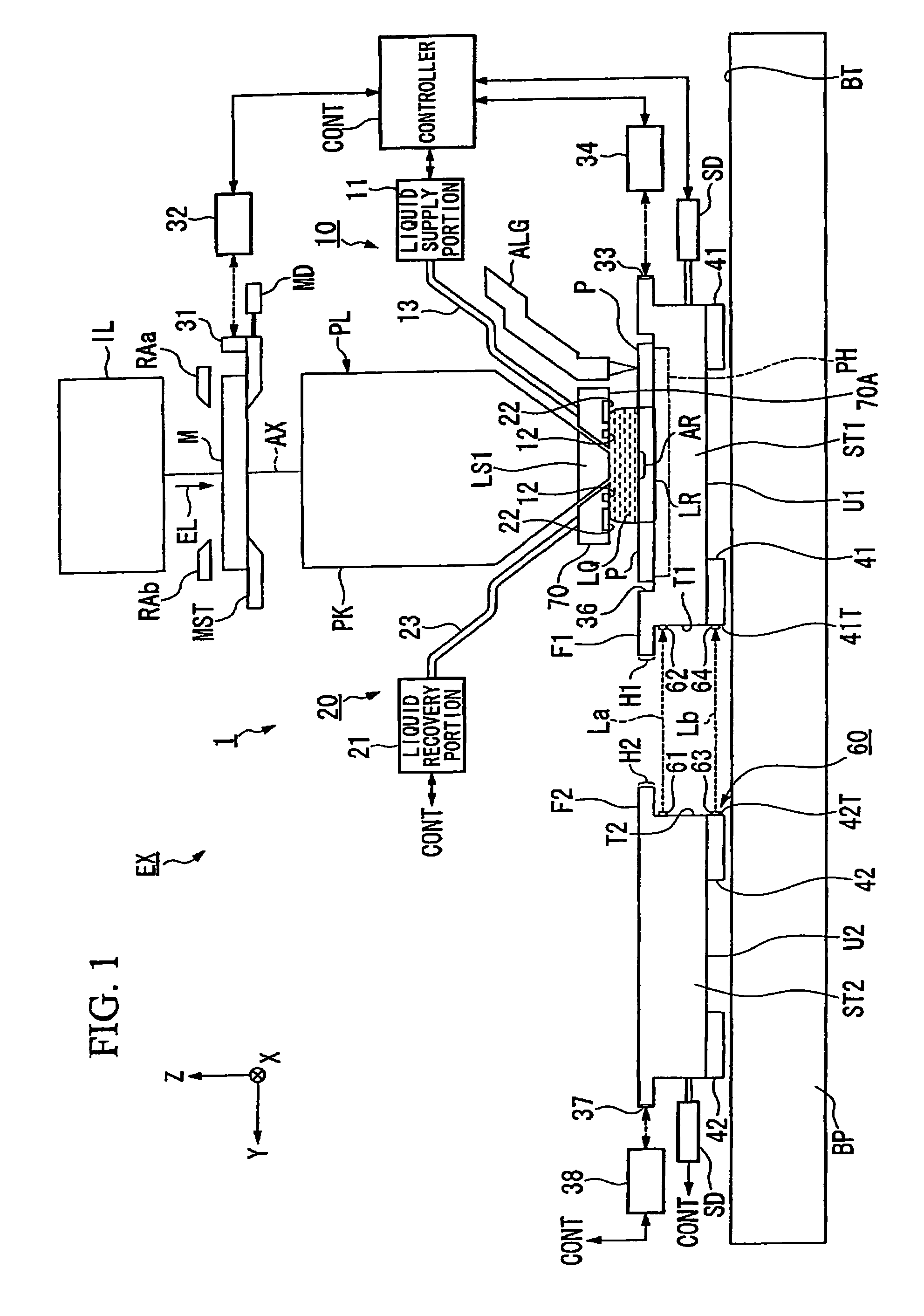
[0022]FIG. 1 is a schematic diagram showing an exposure apparatus in accordance with a first embodiment. In FIG. 1, exposure apparatus EX includes mask stage MST that is movable while holding mask M, with substrate stage ST1 that is movable while holding substrate P, with measurement stage ST2 that is movable while measuring devices related to the exposure process being mounted thereon, with illumination optical system IL that illuminates mask M held by mask stage MST with exposure light EL, with projection optical system PL that projects a pattern image of mask M illuminated with exposure light EL onto substrate P held by substrate stage ST1, and with controller CONT that controls the overall operation of exposure apparatus EX. Substrate stage ST1 and measure stage ST2 are each movably supported on base member BP and are movable independently of each other. On undersurface U1 of substrate stage ST1 are provided gas bearings 41 for supporting substrate stage ST1 in a non-contact man...

second embodiment

[0073]FIG. 6 is a drawing showing a second embodiment. In the following description, with respect to the same or equivalent constituent elements as those in the above-described embodiment, their descriptions will be abridged or omitted. Detecting device 60′ shown in FIG. 6 has both of a function of a light projecting portion emitting detecting light La′ and a function of a light receiving portion receiving the light. Detecting device 60′ is provided on overhang portion H2 of measurement stage ST2. On the other hand, reflecting member 66 having reflecting surface 65 is provided on a position that is located on overhang portion H1 of substrate stage ST1 and faces detecting device 60′. Detecting device 60′ illuminates reflecting surface 65 with detecting light La, receives, at the same time, the reflected light from reflecting surface 65, and detects, based upon the light reception results, whether liquid LQ has leaked from gap G. When liquid LQ does not exist on the optical path of de...

third embodiment

[0076]FIG. 7 is a drawing exposure apparatus EX′ in accordance with a third embodiment. Exposure apparatus EX′ shown in FIG. 7 is such a so-called twin-stage type exposure apparatus as disclosed in, e.g., Japanese Unexamined Patent Publication Hei 10-163099, Japanese Unexamined Patent Publication Hei 10-214783, and Published Japanese Transition 2000-505958, in which two substrate stages ST1′ and ST2′ that are movable while holding a substrate are provided. Also in exposure apparatus EX′ shown in FIG. 7, liquid immersion region LR can be moved between upper surface F1′ of first sure stage ST1′ and upper surface F2′ of second substrate stage ST2′. Further, by providing detecting device 60 (60′) as in the case of the above-described embodiments, liquid LQ having leaked from between first substrate stage ST1′ and second substrate stage ST2′ when moving liquid immersion region LR from the surface of one of the stages of first substrate stage ST1′ and second substrate stage ST2′ to the up...


PUM


Abstract

An exposure apparatus which prevents damages due to leaked out liquid from expanding and can maintain exposure accuracy and measuring accuracy. The exposure apparatus includes first and second stages (ST1, ST2) which can independently move within an XY-plane on an image plane side of a projection optical system (PL); a drive mechanism (SD) which moves the first stage and the second stage together with the stage being close to or in contact with each other; a liquid immersion mechanism (1) which forms a liquid immersion area on an upper plane of at least one of the stages of the first stage and the second stage; and a detecting device (60) which detects liquid leaked out from between the first stage and the second stage.

Description

TECHNICAL FIELD[0001]The present invention relates to an exposure apparatus that exposes a substrate via an optical system and to a device manufacturing method.[0002]The present application claims priority to Japanese Patent Application No. 2004-301639, filed on Oct. 15, 2004, and its content is incorporated herein by reference.BACKGROUND ART[0003]In the photolithography process, which is one of the processes for manufacturing micro-devices such as semiconductor devices or liquid crystal display devices, an exposure apparatus that projects a pattern formed on a mask onto a photosensitive substrate is used. Such an exposure apparatus has a mask stage that supports a mask and a substrate stage that supports a substrate and, while successively moving the mask stage and the substrate stage, projects an image of the pattern of the mask onto the substrate via a projection optical system. By the way, some of such exposure apparatuses include two stages that are movable independently of eac...

Claims


Application Information

Patent Timeline
Patent Type & Authority Patents(United States)
IPC IPC(8): G03B27/42G03B27/52
CPCG03F7/70341G03F7/70525G03F7/70991G03F7/70733G03F7/70716G03F7/2041H01L21/0274
Inventor SHIBUTA, MAKOTO
Owner NIKON CORP
Why Eureka
Try Eureka