Lens driving device

a driving device and lens technology, applied in piezoelectric/electrostriction/magnetostriction machines, instruments, mountings, etc., can solve the problems of generating electromagnetic waves harmful to humans, requiring high power, and reducing the accuracy of driving the lens, so as to minimize the loss of power consumed for driving the lens and achieve accurate and stable driving. , the effect of excellent positioning resolution

Inactive Publication Date: 2008-11-25
SAMSUNG ELECTRO MECHANICS CO LTD
View PDF15 Cites 20 Cited by
  • Summary
  • Abstract
  • Description
  • Claims
  • Application Information

AI Technical Summary

Benefits of technology

[0023]Another aspect of the invention is to provide a lens driving device which can obtain a large displacement or transport range of a lens with low input power to achieve excellent positioning resolution, thereby minimizing loss of power consumed for driving the lens.
[0024]Further another aspect of the invention is to provide a lens driving device which adopts a simple mechanism for guiding the movement of a lens, thereby accurately and stably driving the lens.
[0041]More preferably, the vertical rib has a fixing plate disposed in contact with an upper surface of the piezoelectric body so as to prevent upward disengagement and play of the piezoelectric vibrator.

Problems solved by technology

In addition, the above described lens driving device has the plurality of reduction gears, hindering miniaturization.
Further, it uses an electromagnetic motor, requiring high power, generates electromagnetic waves harmful to humans, and has low positioning resolution of the lens.
However, the zoom lens mechanism 20 of the camera also adopts an electromagnetic motor, thus requiring a plurality of reduction gears, hindering miniaturization.
In addition, it is impossible to prevent generation of electromagnetic waves by the motor.
Further, the mechanism 20 has low positioning resolution, hindering precise control.
It also does not adopt reduction gears for power transmission, thereby simplifying the structure thereof.
However, as the driving rods 36 are essentially fixed, it is impossible to vary the length of the barrel, thus limiting miniaturization.

Method used


Image

  • Lens driving device
  • Lens driving device
  • Lens driving device

Examples


Embodiment Construction

[0058]Exemplary embodiments of the present invention will now be described in detail with reference to the accompanying drawings.

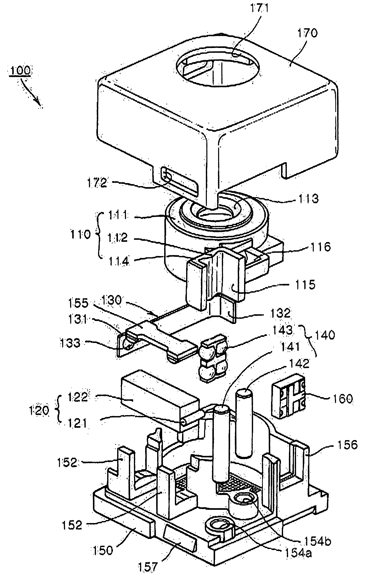
[0059]FIG. 4 is an overall perspective view illustrating a lens driving device according to the present invention, FIG. 5 is an exploded perspective view illustrating the lens driving device according to the present invention, FIG. 6 is a side view illustrating the lens driving device according to the present invention and FIG. 7 is a plan view illustrating the lens driving device according to the present invention.

[0060]As shown in FIGS. 4 to 7, the lens driving device 100 according to the present invention includes a lens barrel 110 with at least one lens housed therein, a piezoelectric vibrator 120 for providing driving power for moving the lens barrel 110 with the lens therein in the optical axis direction, a preload member 130 for compressing the piezoelectric vibrator 120 and a guiding part 140 for guiding the movement of the lens barrel 110.

[0061]As...


PUM


Abstract

A lens driving device includes a lens barrel having a lens holder and an extension part extended from the lens holder. The device also includes a piezoelectric vibrator with a piezoelectric body flexed and bent in response to power application with a friction member in contact with the extension part, thereby providing driving power for transporting the lens barrel. The device further includes a preload member having a free end in resilient contact with a rear end of the piezoelectric body to compress the piezoelectric vibrator against the extension part and a guiding part for guiding the transport of the lens barrel in the optical axis direction. This allows a simplified and miniaturized structure, a large transport range with low input power to achieve excellent resolution of positioning, minimal loss of driving power, simplified mechanism for guiding the transport of the lens, and accurate and stable transport of the lens.

Description

CLAIM OF PRIORITY[0001]This application claims the benefit of Korean Patent Application No. 2006-16337 filed on Feb. 20, 2006, in the Korean Intellectual Property Office, the disclosure of which is incorporated herein by reference.BACKGROUND OF THE INVENTION[0002]1. Field of the Invention[0003]The present invention relates to a lens driving device adopted in an optical apparatus and, more particularly, to a lens driving device having a simplified driving mechanism to accommodate miniaturization and thus capable of minimizing power loss from driving a lens and more accurately driving the lens.[0004]2. Description of the Related Art[0005]In general, optical apparatuses include lens driving devices which move lenses using cam structures, screws or piezoelectric elements. The lens driving devices adopt motors or piezoelectric elements to generate driving power while using cam structures or screws to transmit the driving power.[0006]Therefore, a lens driving device moves a lens to change...

Claims


Application Information

Patent Timeline
Patent Type & Authority Patents(United States)
IPC IPC(8): G02B7/02G02B15/14
CPCG02B7/102G02B7/023G02B7/04G02B7/09H02N2/0065H02N2/02H02N2/08G03B2205/0061
Inventor PAIK, KI MUNLEE, DONG KYUNKOC, BURHANETTINKANG, BYUNG WOO
Owner SAMSUNG ELECTRO MECHANICS CO LTD
Why Eureka
Try Eureka