
Communication apparatus, method and program for realizing P2P communication

a communication apparatus and communication technology, applied in the field of communication apparatus, method and program, can solve the problems of not being able to realize p2p communication in complicated networks, generally very difficult to perform p2p communication, etc., and achieve the effect of improving the security level

Active Publication Date: 2008-11-25
PANASONIC CORP
View PDF8 Cites 18 Cited by
  • Summary
  • Abstract
  • Description
  • Claims
  • Application Information

AI Technical Summary

Benefits of technology

"The present invention provides a communication apparatus, method, and program for realizing P2P communication even in a complicated network environment. The communication apparatus can acquire information about addresses in the network and dynamically change the method for establishing P2P connections based on the network structure and the changes in the network. The communication apparatus can also determine the destination address information and start P2P communication using the destination address information or the sender address information. The invention improves security and processing speed by not configuring unnecessary NAT settings."

Problems solved by technology

Accordingly, it is generally very difficult to perform P2P communication.
However, P2P communication can not be realized in complicated networks only with UPnP•IGD.

Method used


Image

  • Communication apparatus, method and program for realizing P2P communication
  • Communication apparatus, method and program for realizing P2P communication
  • Communication apparatus, method and program for realizing P2P communication

Examples


first embodiment

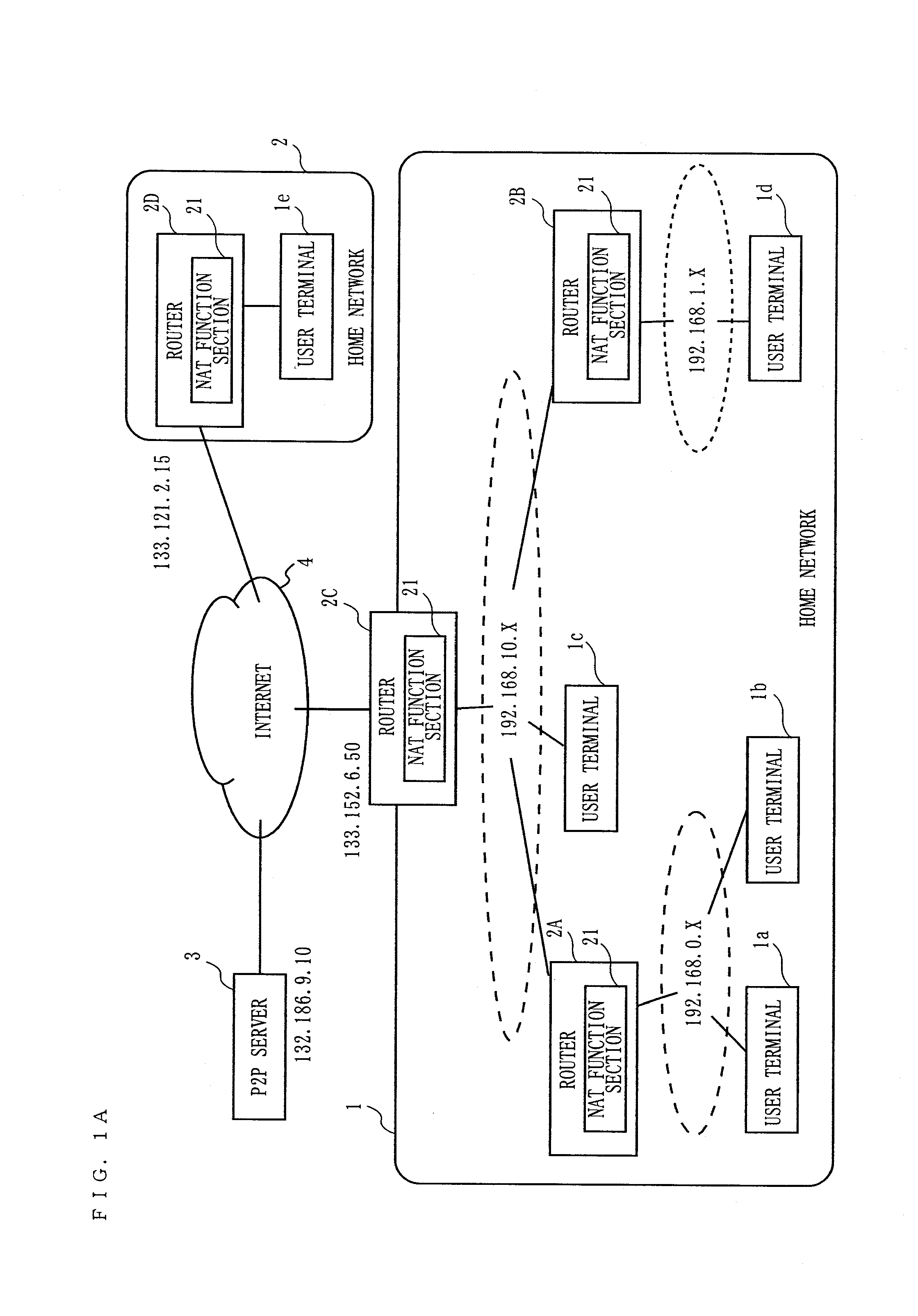
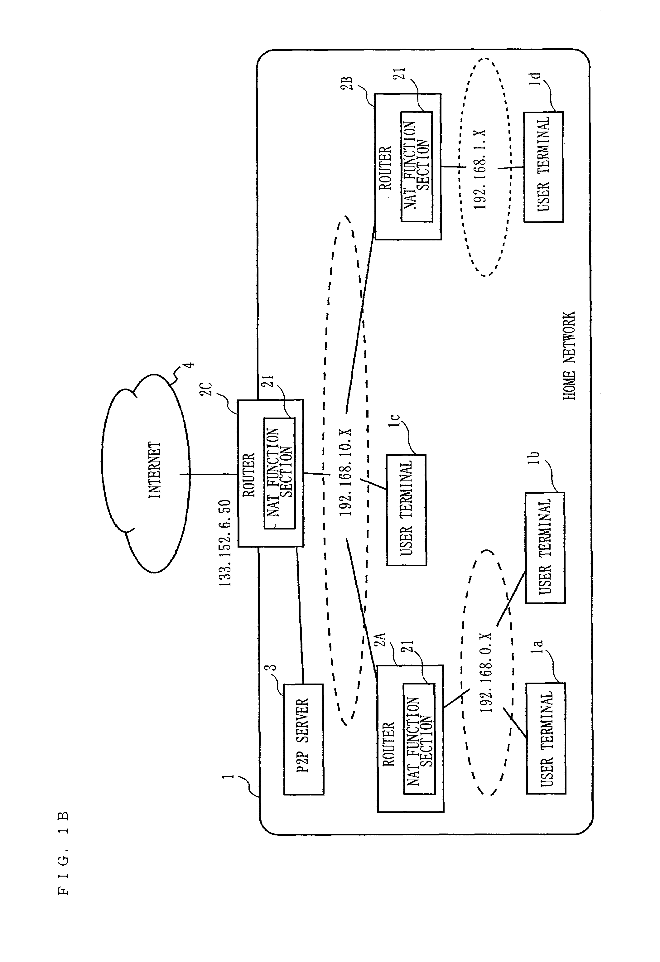
[0089]FIG. 1A is a diagram showing an exemplary structure of a network in which P2P communication control according to a first embodiment of the present invention is performed. In FIG. 1A, the entire network includes a home network 1, a home network 2, a P2P server 3, and the Internet 4. The number of home networks and the number of P2P servers are not limited to those shown in FIG. 1A.

[0090]The home network 1 includes a plurality of routers 2A, 2B and 2C, and a plurality of user terminals 1a, 1b, 1c and 1d. The number of routers and the number of user terminals in the home network 1 are not limited to those shown in FIG. 1A. The routers 2A, 2B and 2C each include a NAT function section 21 for setting an address translation rule for translating address information of an internal network into address information of an external network. The router 2A, 2B and 2C connect the Internet 4 and the home networks (hereinafter, referred to as “subnets”) to each other, or connect a plurality of...

second embodiment

[0213]In a second embodiment, a user terminal first determines by which network structure the user terminal itself is connected to a communication partner, or by which route communication is possible, based on its own address information and address information of a communication partner, and then performs P2P communication. In the second embodiment, in the case where there are two or less routers from the user terminal to the Internet, it can be mostly determined with which destination address P2P connection can be established. The network structure, the identification information registration processing, and the communication information exchange processing are substantially the same as those in the first embodiment, and thus will not be described. FIG. 19A and FIG. 19B use representation (x−y). “x” represents the number of routers (the number of levels of routers) upstream with respect to the user terminal, and “y” represents the number of routers (the number of levels of routers...

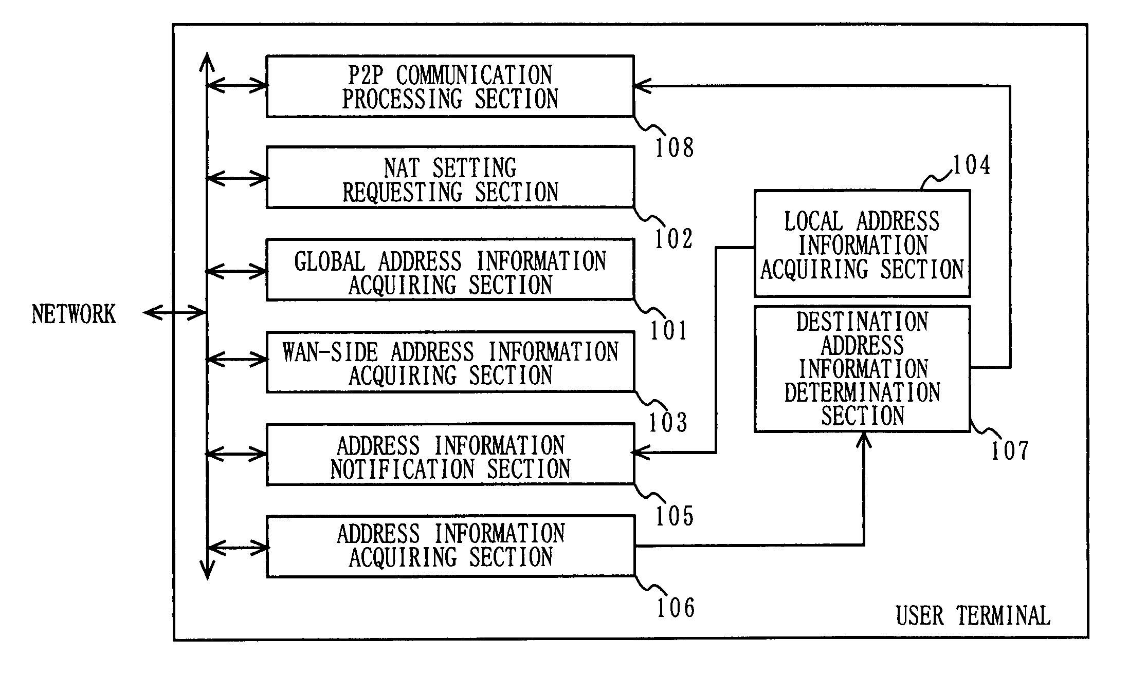
third embodiment

[0263]FIG. 20 is a block diagram showing a detailed functional structure of a communication apparatus, which is a user terminal for performing P2P communication processing according to the present invention. As shown in FIG. 20, the communication apparatus includes an identification information recording section 201, a self and partner address information memory section 202, an address information comparison and determination section 203, a communication path establishment determination section 204, a control section 205, a connection establishment method switching section 206, an application processing section 207, an identification information registration sending section 208, an address information notification request sending and response receiving section 209, a static NAT setting requesting section 210, a communication start request sending and response receiving section 211, a communication path connection request sending and response receiving section 212, a P2P communicatio...


PUM


Abstract

A communication apparatus includes a global address information acquiring section for acquiring first global address information, a WAN-side address information acquiring section for acquiring first WAN-side address information, and a local address information acquiring section for acquiring first local address information. Moreover, the apparatus includes an address information notification section for notifying the first global address information, the first WAN-side address information, and the first local address information to a communication partner apparatus. Furthermore, the apparatus includes an address information acquiring section for acquiring second global address information, a second WAN-side address information, and a second local address information assigned to the communication partner apparatus. The communication apparatus determines a method by which P2P connection can be established based on the first and second global address information, the first and second WAN-side address information, and the first and second local address information.

Description

BACKGROUND OF THE INVENTION[0001]1. Field of the Invention[0002]The present invention relates to a communication apparatus, method and program used in a communication network, and more specifically to a communication apparatus, method and program for realizing peer-to-peer communication (hereinafter, referred to as “P2P communication”).[0003]2. Description of the Relayed Art[0004]As a technology for connecting a plurality of user terminals in a house to the Internet using one global address, the NAT technology (Network Address Translation; conceptually encompasses Network Address Port Translation (NAPT)) using an address translation rule is used. According to the NAT technology, for routing a message from the LAN (Local Area Network) side to the WAN (Wide Area Network) side, a router translates sender address information into WAN-side address information. For routing a message from the WAN side to the LAN side, the router translates destination address information from WAN-side addr...

Claims


Application Information

Patent Timeline
Patent Type & Authority Patents(United States)
IPC IPC(8): H04L12/56H04L12/28
CPCH04L12/2854
Inventor KOKADO, TAKESHI
Owner PANASONIC CORP
Learn More