Portable radio communication apparatus provided with boom portion with through hole

a radio communication apparatus and boom portion technology, applied in the field can solve the problems of low operability, disadvantageous off-balance of portable radio communication apparatus, and disadvantageous user of portable radio communication apparatus, and achieve the effect of easy bilateral or horizontal balance, and easy operation

Active Publication Date: 2008-11-25
PANASONIC INTELLECTUAL PROPERTY CORP OF AMERICA
View PDF29 Cites 18 Cited by
  • Summary
  • Abstract
  • Description
  • Claims
  • Application Information

AI Technical Summary

Benefits of technology

[0014]It is an object of the present invention to provide a portable radio communication apparatus which can solve the above-mentioned disadvantages, which can be constituted to be bilaterally symmetric so that even if the portable radio communication apparatus is put into his pocket of the user, the user does not feel uncomfortable and so that if the portable radio communication apparatus is suspended from his neck, the potable radio communication apparatus can be suspended in a well-balanced manner while maintaining better antenna radiation pattern, and which can further improve both performance and design.
[0035]According to the portable radio communication apparatus of one aspect of the present invention, a radio wave can be transmitted and received without using any external antenna as used in the prior art. It is therefore possible to solve such a conventional disadvantage that the external antenna is sometimes caught in his pocket when the portable radio communication apparatus is taken out of his pocket. Further, since at least one through hole is formed in the space between the boom portion and the housing, the portable radio communication apparatus can be suspended from his neck with a strap attached to the boom portion. Also in this case, it is unnecessary to use the conventional external antenna. Therefore, the portable radio communication apparatus can be designed to be bilaterally symmetric, and the portable radio communication apparatus can be easily well bilaterally or horizontally balanced when the portable radio communication apparatus is suspended from his neck.
[0036]According to the portable radio communication apparatus of another aspect of the present invention, a radio wave can be transmitted and received without using any external antenna as used in the prior art. It is therefore possible to solve such a conventional disadvantage that the external antenna is sometimes caught in his pocket when the portable radio communication apparatus is taken out of his pocket. Further, since at least one through hole is formed in the strap attachment portion, the portable radio communication apparatus can be suspended from his neck with a strap attached to the through hole. Also in this case, it is unnecessary to use the conventional external antenna. Therefore, the portable radio communication apparatus can be designed to be bilaterally symmetric, and the portable radio communication apparatus can be easily well bilaterally or horizontally balanced when the portable radio communication apparatus is suspended from his neck.

Problems solved by technology

Further, when the portable radio communication apparatus is suspended from his neck without putting it into his pocket, the center of gravity of the portable radio communication apparatus 151 deviates from the center thereof due to its asymmetric structure, as shown in FIG. 34, in which the external antenna 153 is mounted on either the upper right or upper left end portion of the portable radio communication apparatus 151, so that there has been such a problem that the portable radio communication apparatus 151 disadvantageously becomes off balanced.
JP 2002-516503 A has such a complicated structure that a housing, a first flip and a second flip are provided, and the first flip including the antenna element is large in size, the portable radio communication apparatus disadvantageously becomes a hindrance to the user and is low in operability.

Method used


Image

  • Portable radio communication apparatus provided with boom portion with through hole
  • Portable radio communication apparatus provided with boom portion with through hole
  • Portable radio communication apparatus provided with boom portion with through hole

Examples


first preferred embodiment

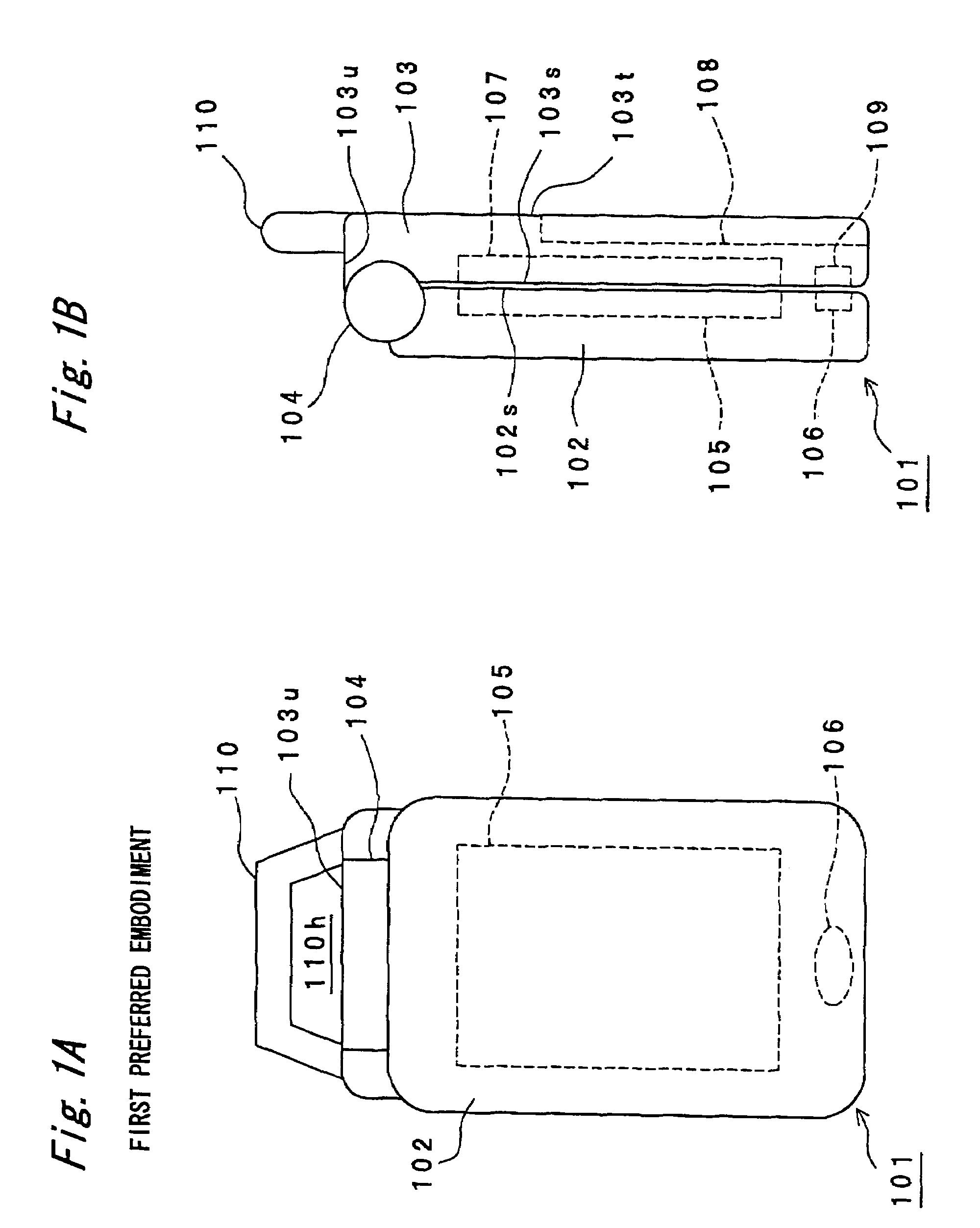
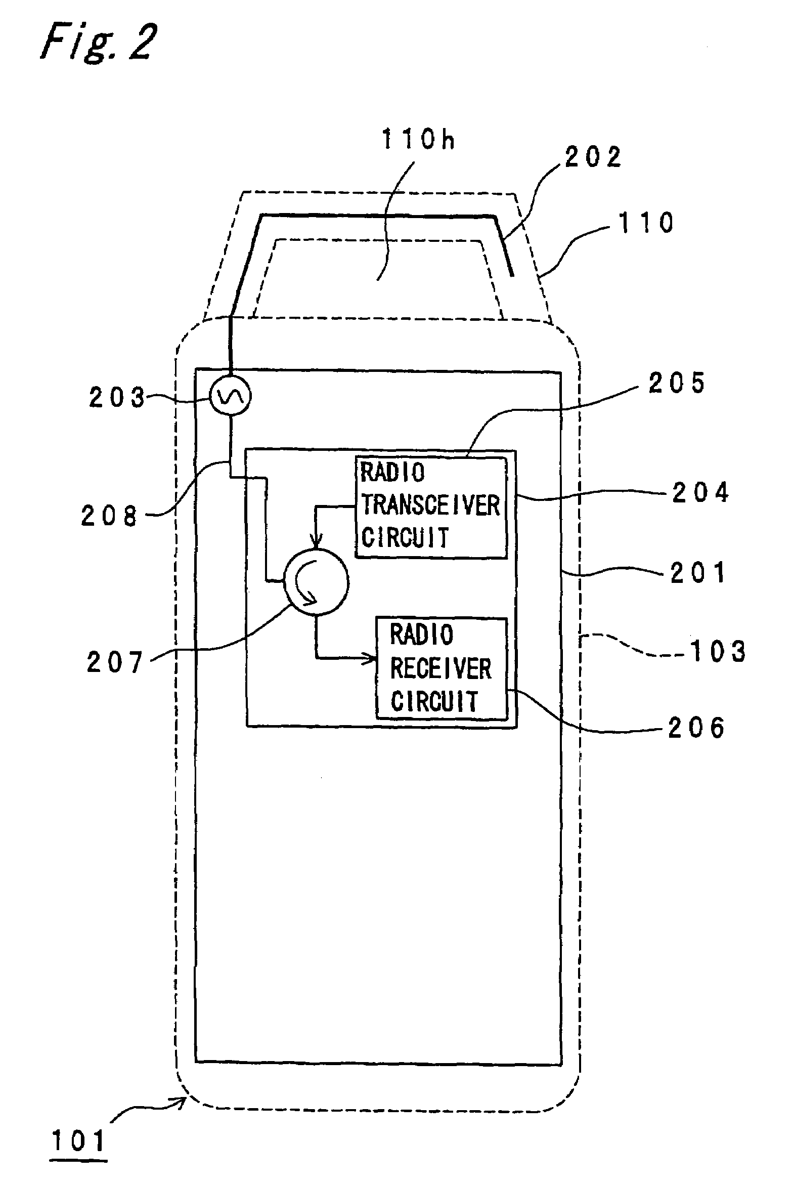
[0074]FIG. 1A is a plan view of a portable radio communication apparatus 101 of a first preferred embodiment according to the present invention in a folding state, and FIG. 1B is a side view thereof. FIG. 2 is a plan view of the portable radio communication apparatus 101 shown in FIG. 1A with a perspective view showing a part of a lower housing 103 thereof.

[0075]Referring to FIGS. 1A and 1B, the portable radio communication apparatus 101 is constituted by including the following:

[0076](a) an approximately rectangular parallelepiped upper housing 102;

[0077](b) an approximately rectangular parallelepiped lower housing 103;

[0078](c) a hinge portion 104 which connects the upper housing 102 with the lower housing 103;

[0079](d) a display 105 and a sound hole portion 106 for a speaker provided in the upper housing 102; and

[0080](e) a keyboard 107;

[0081](f) a rechargeable battery 108; and

[0082](g) a microphone 109 and a boom portion 110 which are provided within the lower housing 103.

[0083]...

second preferred embodiment

[0094]The first preferred embodiment has been described with reference to an example of forming the antenna element 202 which is a monopole antenna made of a strip conductor of the boom portion 110. Alternatively, the other antenna configurations may be used. As examples of the other configurations, portable radio communication apparatuses 101c, 101d, 101e, 101f, 101g and 101h of second to seventh preferred embodiments according to the present invention will be described with reference to FIGS. 5, 6, 7, 8, 9 and 10A and 10B.

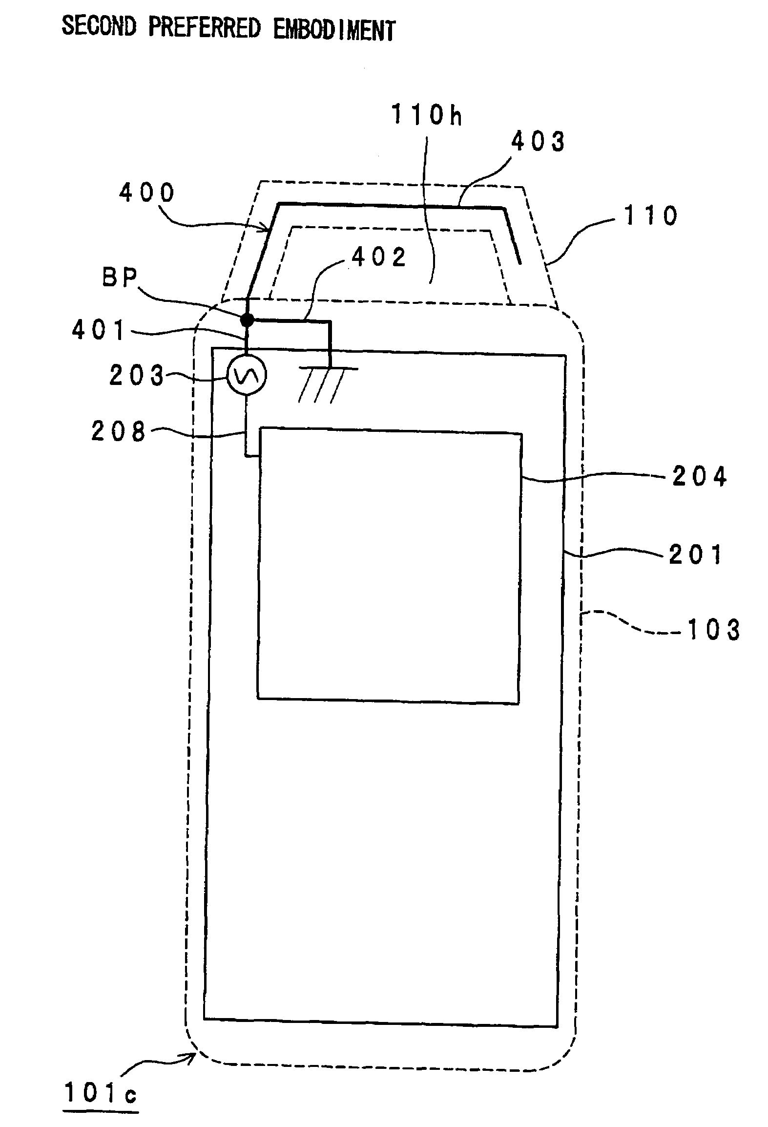
[0095]FIG. 5 is a plan view of the portable radio communication apparatus 101c which employs an inverted-F antenna element 400, with a perspective view showing a specific configuration example of the portable radio communication apparatus 101c of a second preferred embodiment according to the present invention.

[0096]Referring to FIG. 5, the inverted-F antenna element 400 is constituted by including a first antenna portion 401, a second antenna portion 402 and a t...

third preferred embodiment

[0099]FIG. 6 is a plan view of the portable radio communication apparatus 101d which employs a helical antenna element 500 with a perspective view showing an example of the portable radio communication apparatus 101d of the third preferred embodiment according to the present invention. The helical antenna element 500 is formed on the interior of the boom portion 110 and an interior of the lower housing 103 by using, for example, a strip conductor, and characterized by including a helical conductor 501 of helical shape on a part of the middle of the strip conductor. One end of the helical antenna element 500 is connected with the radio communication circuit 204 through the feeding point 203 and the feeding cable 208. The portable radio communication apparatus 101d of the present preferred embodiment exhibits actions and advantageous effects similar to those of the portable radio communication apparatus 100 shown in FIGS. 1A and 1B except that the helical antenna element 500 is formed...


PUM


Abstract

A portable radio communication apparatus is provided with a boom portion having both ends connected with a housing of the portable radio communication apparatus and having a central portion located between both ends. In the portable radio communication apparatus, at least one through hole is formed between the boom portion and the housing. The boom portion includes a central portion and two end portions. The central portion extends in parallel to a width direction of the portable radio communication apparatus, and the two end portions are bent respectively from both ends of the central portion.

Description

BACKGROUND OF THE INVENTION[0001]1. Field of the Invention[0002]The present invention generally relates to a portable radio communication apparatus, and in particular, relates to a portable radio communication apparatus having a feature in a supporting device or a supporting member of communication equipment such as a portable telephone terminal apparatus or the like.[0003]2. Description of the Related Art[0004]Recently, portable radio communication apparatuses such as portable telephone terminal apparatuses or the like have been increasingly made smaller in size and thinner. In addition, the portable radio communication apparatus has been used not only as a conventional telephone but also transformed to a data terminal apparatus for transmitting and receiving E-mails and for viewing web pages through WWW (World Wide Web). Due to this, a display for the portable radio communication apparatus has been made larger in size. In these circumstances, folding-type portable telephone termin...

Claims


Application Information

Patent Timeline
Patent Type & Authority Patents(United States)
IPC IPC(8): H04B1/38H01Q1/24H01Q1/27H01Q9/42H04M1/05
CPCH01Q1/242H01Q1/273H01Q9/42H04M1/05H04B1/38
Inventor IWAI, HIROSHIKAMAEGUCHI, SHINJIYAMADA, KENICHIASAHINA, TOSHIHIROYAMAMOTO, ATSUSHI
Owner PANASONIC INTELLECTUAL PROPERTY CORP OF AMERICA
Why Eureka
Try Eureka