Storage System and Operation Method Thereof

a storage system and operation method technology, applied in the field of storage systems and operation methods, can solve problems such as unmentioned, and achieve the effect of maximising the throughput of storage devices

Inactive Publication Date: 2010-05-20
HITACHI LTD
View PDF10 Cites 30 Cited by
  • Summary
  • Abstract
  • Description
  • Claims
  • Application Information

AI Technical Summary

Benefits of technology

[0011]According to the present invention, storage resources can be efficiently assigned to storage areas in a well-balanced manner in terms of performance and capacity.

Problems solved by technology

However, it could not be said that these conventional techniques are capable of optimally assigning performance resources, e.g., data I / O performance, and capacity resources represented by a storage capacity in a storage apparatus in terms of performance requirements required for the storage apparatus so that the storage resources of the storage apparatus can be used with sufficient efficiency.

Method used


Image

  • Storage System and Operation Method Thereof
  • Storage System and Operation Method Thereof
  • Storage System and Operation Method Thereof

Examples


first embodiment

System Configuration

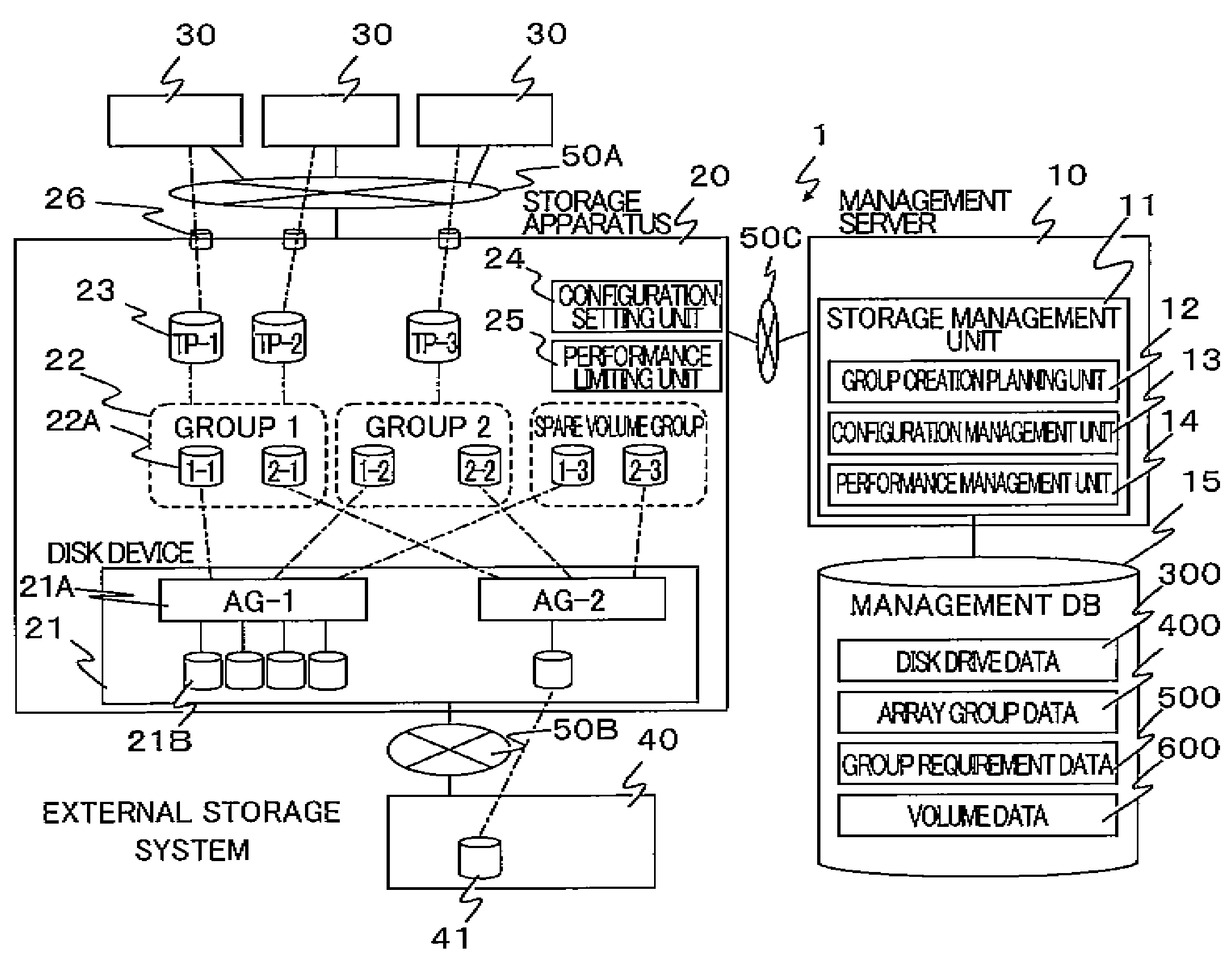
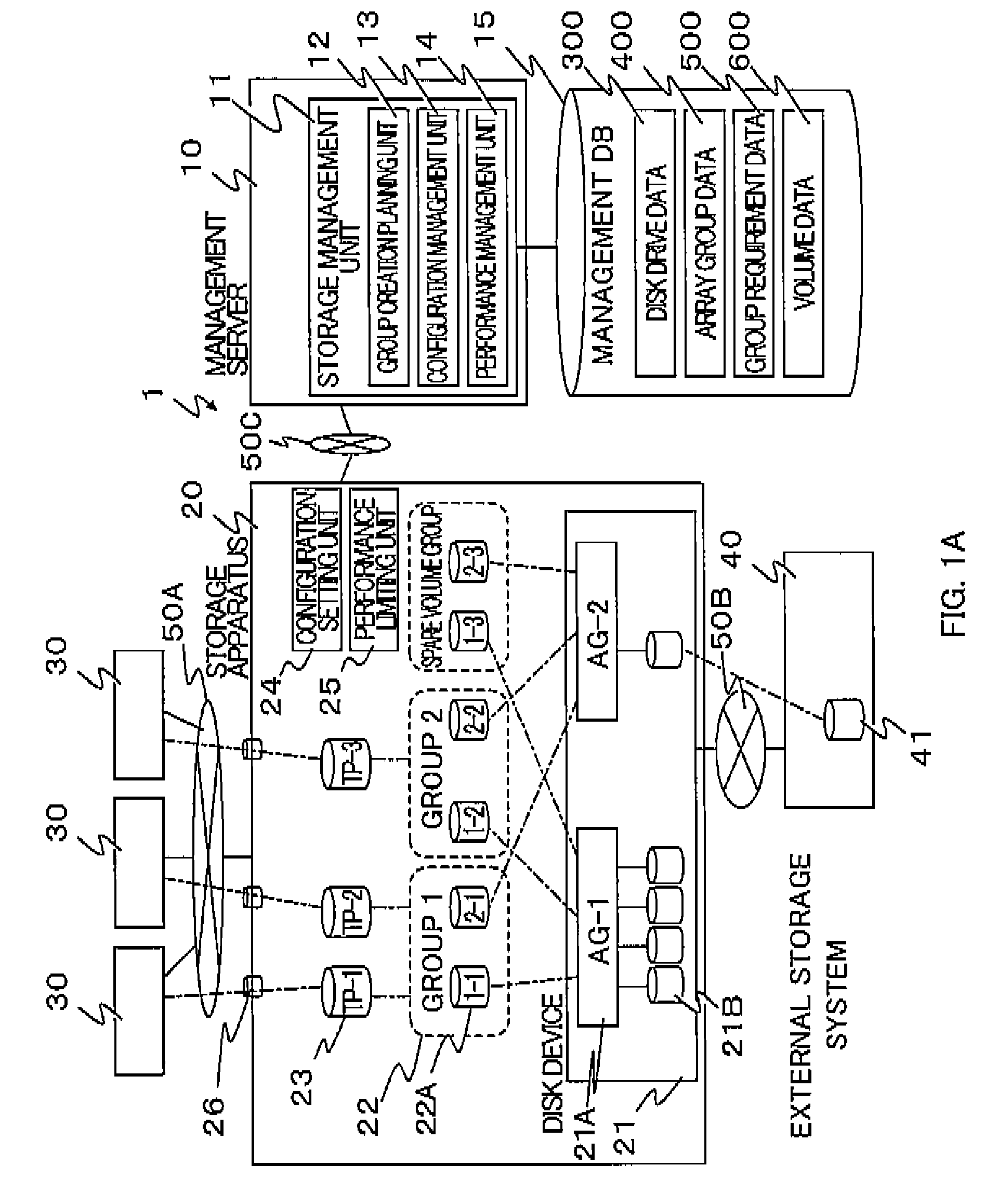
[0042]FIG. 1A shows a hardware configuration of a storage system 1 for explaining a first embodiment of the present invention. As shown in FIG. 1A, this storage system 1 includes a management server apparatus 10, a storage apparatus 20, service server apparatuses 30, and an external storage system 40.

[0043]Each of the service server apparatuses 30 and the storage apparatus 20 are coupled to each other via a communication network 50A, and the storage apparatus 20 and the external storage system 40 are coupled to each other via a communication network 50B. In the present embodiment, these networks are each a SAN (Storage Area Network) by using a Fibre Channel (hereinafter, referred to as an “FC”) protocol. Further, the management server apparatus 10 and the storage apparatus 20 are also coupled to each other via a communication network SOC which is a LAN (Local Area Network) in the present embodiment.

[0044]The service server apparatus 30 is a computer (an informati...

second embodiment

[0122]Next, a second embodiment of the present invention will be described. In the first embodiment, a configuration has been described in which logical volumes 22A are newly created from an array group 21A and assigned to each group (Tier) used by an application. However, in the present embodiment, logical volumes 22A are assumed to have already been created, and the present invention is applied to the case where some of the logical volumes 22A are being used.

[0123]A system configuration and configurations of data tables are the same as those of the first embodiment, so that only changes of processing flows will be described below.

[0124]In the present embodiment, in the entire flow of FIG. 9, a step of acquiring information on an existing volume 22A is added at the time of recognition of the storage apparatus 20 in SAN environment shown in S901. Further, in the volume creation planning process shown in S902 (refer to FIG. 12 for a detailed flow), the calculation of performance / capa...

third embodiment

[0144]The first and second embodiments each have a configuration in which logical volumes 22A are used by grouping them into groups 22, or when necessary, by configuring the group with a pool of virtual volumes 23. However, in the present embodiment, such grouping is not made, and performance and capacity are set for each logical volume 22A.

[0145]FIG. 26 shows a system configuration of the third embodiment. As is clear from the drawing, the system configuration of this embodiment is the same as those of the first and second embodiments, except for the point that groups 22 are not formed. In other words, for each application of the service server apparatus 30, a single logical volume 22A is assigned. Incidentally, the configurations of data tables are the same as those of the first and second embodiments.

[0146]FIG. 27 shows an example of a process flow changed for this embodiment. In this embodiment, the requirement setting (S1202 of FIG. 12) of each group 22 made by the administrato...


PUM


Abstract

To efficiently assign storage resources to storage areas in a well-balanced manner in terms of performance and capacity, provided is a storage system in which, for a storage apparatus including a disk array group providing a logical volume to be assigned to an application, a storage management unit holds the throughput, response time, and storage capacity of the array group; receives performance density being a ratio between a throughput and a storage capacity, and a requirement on a storage capacity required for the logical volume; and assigns the throughput to the logical volume on the basis of the received performance density and the capacity requirement with the throughput of the array group set as an upper limit, and assigns, to the logical volume, a storage area determined on the basis of the assigned throughput and the received capacity requirement.

Description

CROSS-REFERENCE TO RELATED APPLICATION[0001]The present application claims priority from Japanese Patent Application No. 2008-294618 filed on Nov. 18, 2008, which is herein incorporated by reference.BACKGROUND OF THE INVENTION[0002]1. Field of the Invention[0003]The present invention relates to a storage system and an operation method thereof, and more particularly to a storage system capable of efficiently assigning storage resources as storage areas in a well-balanced manner in terms of performance and capacity, and an operation method thereof.[0004]2. Related Art[0005]In recent years, with a main object to reduce system operation cost, optimization in the use of storage resources by storage hierarchization has been in progress. In storage hierarchization, storage apparatuses in the client's storage environment are categorized in accordance with their properties, and are used depending on requirements, so that effective use of resources is achieved.[0006]To achieve this object, te...

Claims


Application Information

Patent Timeline
Patent Type & Authority Applications(United States)
IPC IPC(8): G06F13/00G06F12/00
CPCG06F3/0605G06F3/0631G06F13/4022G06F3/0653G06F3/067G06F3/0632
Inventor TAKAMATSU, KAZUKIBENIYAMA, NOBUOOKAMOTO, TAKUYA
Owner HITACHI LTD
Why Eureka
Try Eureka