Liquid level detector

a detector and liquid level technology, applied in the direction of liquid/fluent solid measurement, instruments, machines/engines, etc., can solve the problem of small increase in the cost of manufacturing the plurality of types of arms, and achieve the effect of reducing the manufacturing cos

Active Publication Date: 2008-12-02
DENSO CORP
View PDF24 Cites 45 Cited by
  • Summary
  • Abstract
  • Description
  • Claims
  • Application Information

AI Technical Summary

Benefits of technology

[0012]The present invention has been accomplished in view of the above problems. It is an object of the present invention to provide a liquid level detector, the manufacturing cost of which is reduced.

Problems solved by technology

Therefore, it is easy to manufacture a plurality of types of arms, and an increase in the cost of manufacturing the plurality of types of arms is small.

Method used


Image

  • Liquid level detector
  • Liquid level detector
  • Liquid level detector

Examples


first embodiment

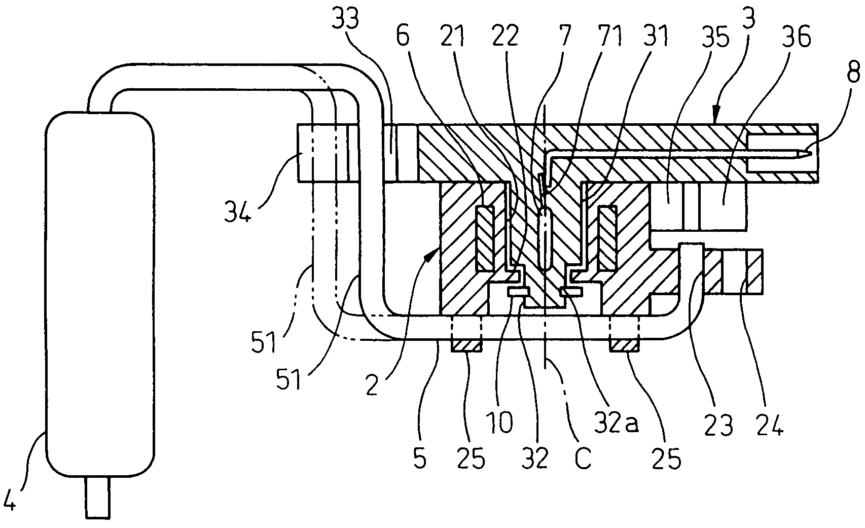
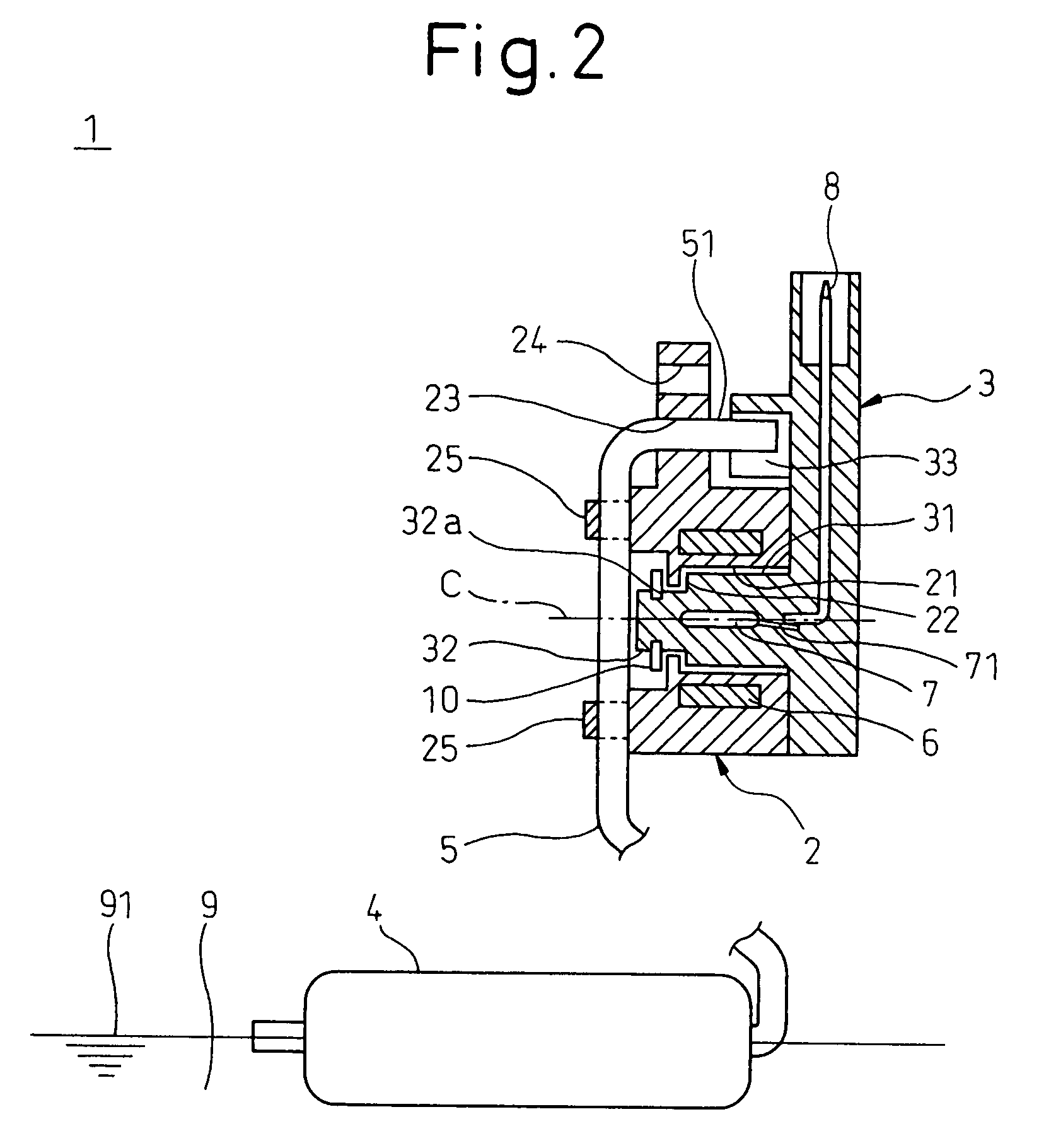
[0070]FIG. 2 is a sectional view showing the fuel level gauge 1 of the first embodiment taken on line II-II in FIG. 1.

[0071]In this connection, in FIGS. 1 and 2, the upper part indicates an upper part of the fuel level gauge 1 attached to the automobile concerned.

[0072]FIG. 3 is a partially sectional view taken on line III-III in FIG. 1 showing the fuel level gauge 1 of the first embodiment of the present invention.

[0073]FIG. 4 is a view showing a model for explaining a state of magnetization and a distribution of the magnetic flux of the magnet 6 in the fuel level gauge 1 of the first embodiment of the present invention.

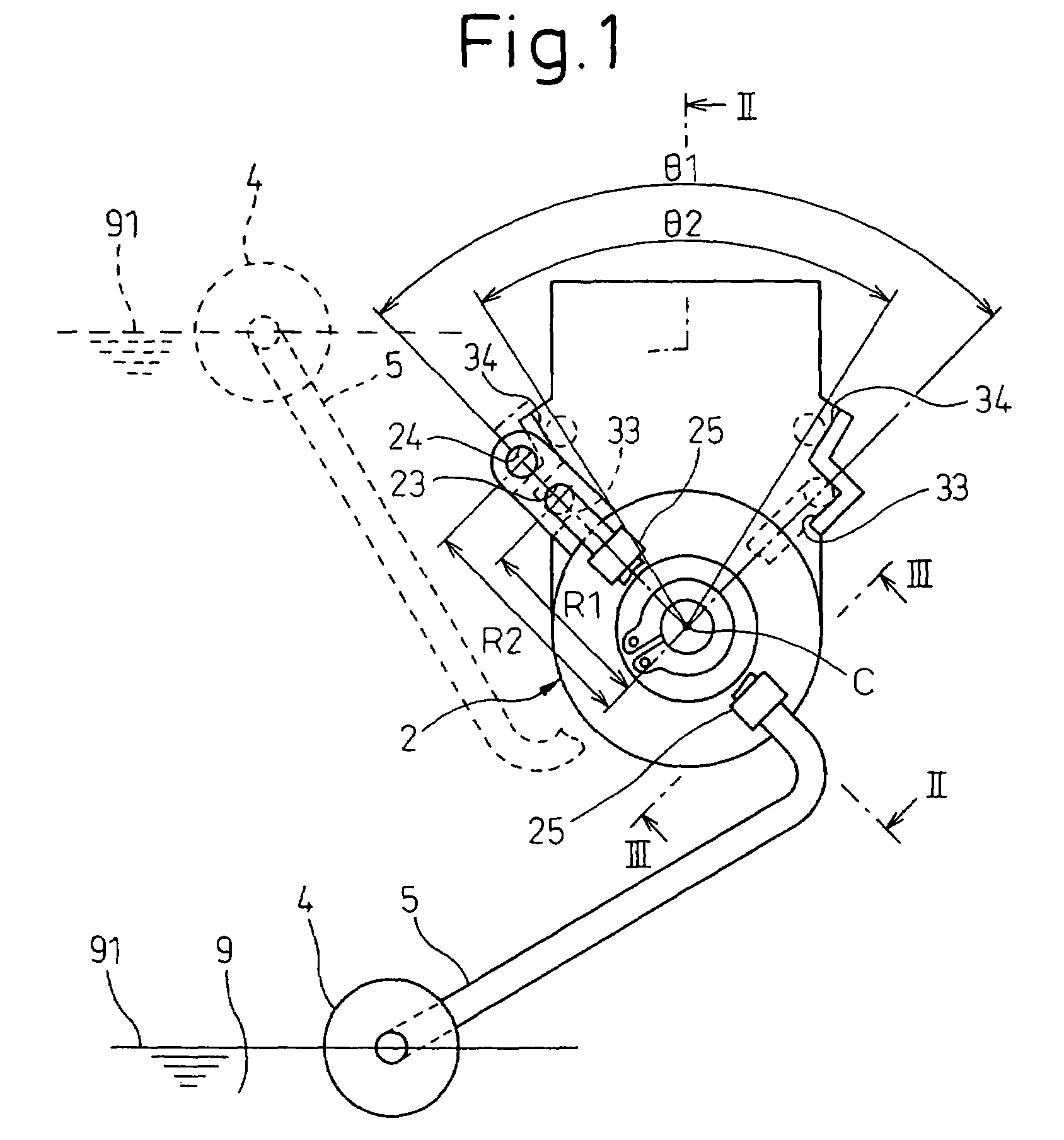
[0074]The fuel gauge 1 is fixed in a fuel tank (not shown), in which liquid fuel 9 is accommodated, so as to detect the liquid level 91.

[0075]The magnet holder 2, which is a rotary member, is made of, for example, resin. As shown in FIG. 2, the magnet 6, which is a permanent magnet used as a displacement member, is fixed to the magnet holder 2, and the magnet holder...

second embodiment

[0100]FIG. 6 is a sectional view taken on line VI-VI in FIG. 5 showing the fuel level gauge 1 of the present invention.

[0101]In the fuel level gauge 1 of the second embodiment of the present invention, shapes of the body 3 and the arm 5 are changed from those of the fuel level gauge 1 of the first embodiment of the present invention.

[0102]As shown in FIG. 6, in the arm 5, the position of the stopper 51, which is a stopper portion, is changed to a position between the magnet holder 2 and the float 4. In the fuel level gauge 1 of the second embodiment of the present invention, the stopper 51 is also formed in parallel with the rotary shaft C of the magnet holder 2. At the position of the stopper 51 in the fuel level gauge 1 of the first embodiment of the present invention, as shown in FIG. 6, the fixing portion 52 for fixing the stopper 51 to the magnet holder 2 is formed. The fixing portion 52 is also formed in parallel with the rotary shaft C of the magnet holder 2.

[0103]According t...

third embodiment

[0111]FIG. 8 is a sectional view taken on line VIII-VIII in FIG. 7 showing the fuel level gauge 1 of the present invention.

[0112]In the fuel level gauge 1 of the third embodiment of the present invention, shapes of the body 3 and the magnet holder 2 are changed from those of the fuel level gauge 1 of the second embodiment of the present invention.

[0113]The first stopper 33 and the second stopper 34, which are provided in the body 3 of the fuel level gauge of the first embodiment of the present invention, are added to the body 3 as the third stopper 35 and the fourth stopper 36 as shown in FIG. 7. Instead of the fixing hole 26 of the magnet holder 2 of the fuel level gauge of the second embodiment of the present invention, the first fixing hole 23 and the second fixing hole 24, which are provided by the magnet holder 2 of the fuel level gauge of the first embodiment of the present invention, are provided in the magnet holder 2 as shown in FIG. 8.

[0114]On the other hand, the shape of ...


PUM


Abstract

Two pairs of regulating means, that is, the first stopper and the second stopper, which regulate a rotary angle range of the magnet holder when the first stopper and the second stopper come into contact with the stopper of the arm integrally fixed to the magnet holder, are provided in the body which is a fixing member, and the rotary angle range of the magnet holder regulated by one pair of stoppers is made to be different from the rotary angle range of the magnet holder regulated by the other pair of stoppers. Due to the foregoing, when the expensive body is made to be a common part and a plurality of types of inexpensive arms are manufactured, the fuel level gauge can be provided, an increase in the manufacturing cost of which is suppressed, which can cope with rotary angle ranges of the plurality of types of arms.

Description

CROSS REFERENCE TO RELATED APPLICATIONS[0001]This application is a divisional of U.S. patent application Ser. No. 11 / 004,937, filed on Dec. 7, 2004 which is based on Japanese Patent Application No. 2004-74891 filed on Mar. 16, 2004, the disclosures of which are incorporated herein by reference.BACKGROUND OF THE INVENTION[0002]1. Field of the Invention[0003]The present invention relates to a liquid level detector for detecting a level of a liquid stored in a container. More particularly, the present invention relates to a non-contact type liquid level detector in which a magnetoelectric conversion element is used.[0004]2. Description of the Related Art[0005]This type liquid level detector is used, for example, for monitoring the amount of fuel accommodated in a fuel tank of an automobile.[0006]For example, this type liquid level detector includes: a float which floats on liquid, the level of which is an object to be measured; a magnet holder for holding a magnet and having a hole por...

Claims


Application Information

Patent Timeline
Patent Type & Authority Patents(United States)
IPC IPC(8): G01F23/32G01F23/38
CPCG01F23/363G01F23/38
Inventor MIYAGAWA, ISAO
Owner DENSO CORP
Why Eureka
Try Eureka