Illumination device and light guide plate

a technology of illumination device and light guide plate, which is applied in the direction of lighting device details, lighting and heating apparatus, instruments, etc., can solve the problems of low light utilization efficiency of light guide plate, limited light-emitting area of emergent surface, and non-uniform illumination, etc., to suppress luminance non-uniformity and increase the amount of display light

Inactive Publication Date: 2008-12-02
138 EAST LCD ADVANCEMENTS LTD
View PDF39 Cites 12 Cited by
  • Summary
  • Abstract
  • Description
  • Claims
  • Application Information

AI Technical Summary

Benefits of technology

[0007]An advantage of some aspects of the invention is to increase the amount of display light and suppress luminance nonuniformity by forming appropriate patterns on faces of a light guide plate.
[0009]For example, the illumination device is suitably used as a backlight unit in a liquid crystal display device. The illumination device includes a plurality of light sources, and a light guide plate having an incident end face on which light from the light sources is incident. As the light sources, for example, LEDs are used. Fine linear grooves discontinuously extend on a reflecting surface in the propagating direction of the light from the light sources to form a diffusing pattern. Light emerging from the reflecting surface is diffused by being refracted by the fine grooves. In this way, the diffusing pattern sufficiently diffuses the incident light perpendicularly to the propagating direction of the light. Consequently, it is possible to suppress luminance nonuniformity due to insufficient light diffusibility.
[0011]Preferably, a reflection sheet is provided on a side of the reflecting surface of the light guide plate. Light emerges from the reflecting surface when the angle with respect to the reflecting surface exceeds the critical angle, it is reflected by the reflection sheet, and returns into the light guide plate. The light emerging from the reflecting surface is diffused by refraction by the diffusing pattern. Consequently, the light can be diffused more satisfactorily.
[0012]Preferably, the light guide plate has an emergent surface, and a plurality of prisms are provided on the emergent surface. For example, the prisms are formed of grooves of substantially inverted triangular cross section. With the prisms, light propagating inside the light guide plate can be efficiently reflected, and the direction of the light can be changed. This increases the amount of light emerging from the emergent surface.
[0017]An electrooptical device according to another aspect of the invention includes a display panel, and the above illumination device used as a backlight of the display panel. The electrooptical device enhances the utilizing efficiency of light from the light sources, and increases the light-emitting area. An electronic apparatus according to a further aspect of the invention includes the electrooptical device as a display section.
[0019]Preferably, the emergent surface has prisms extending perpendicularly to a direction in which the light is incident on the incident end face. By forming the prisms, light propagating inside the light guide plate can be efficiently reflected, and the direction of the light can be changed. Consequently, the amount of light emerging from the emergent surface is increased.

Problems solved by technology

In the above light guide plate, however, when a point light source, such as an LED, is used, luminance nonuniformity is caused because light diffusibility is insufficient.
For this reason, the light utilizing efficiency of the light guide plate is not high, and the light-emitting area of the emergent surface is limited.

Method used


Image

  • Illumination device and light guide plate
  • Illumination device and light guide plate
  • Illumination device and light guide plate

Examples


Embodiment Construction

[0032]Preferred embodiments of the invention will be described below with reference to the drawings.

Configuration of Liquid Crystal Display Device

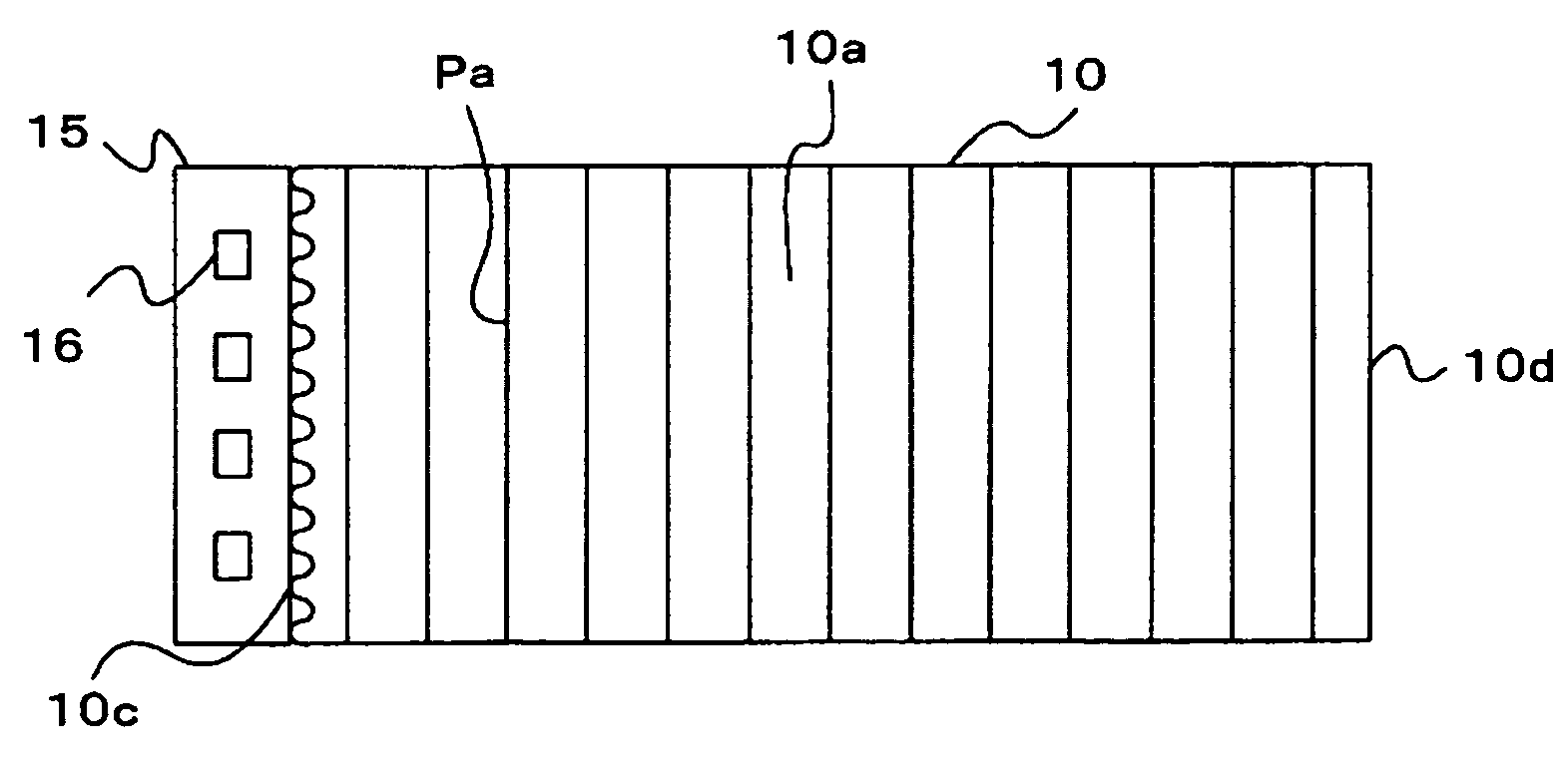
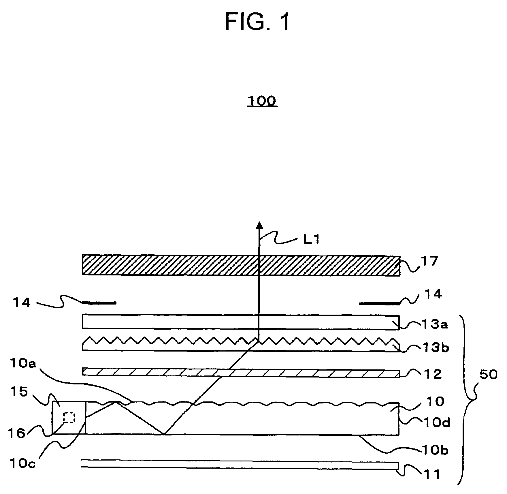
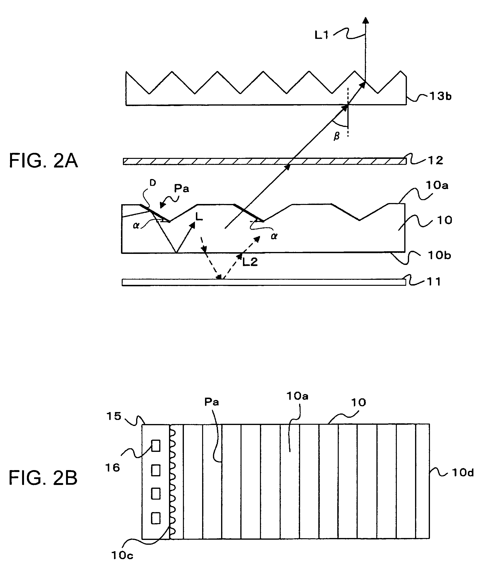
[0033]FIG. 1 schematically shows the configuration of a liquid crystal display device to which an illumination device according to an embodiment of the invention is applied. Referring to FIG. 1, an illumination device 50 according to an embodiment of the invention is of a surface-emitting type, and is used as a backlight unit in the liquid crystal display device 100. The illumination device 50 includes a light guide plate 10 having a light source 15 at an end thereof, a reflection sheet 11 disposed on the lower side of the light guide plate 10, and a diffusing sheet 12 and two prism sheets 13a and 13b disposed on the upper side of the light guide plate 10. The illumination device 50 is bonded to a liquid crystal panel 17 with a double-faced tape 14. Light L1 emerging from the light guide plate 10 passes through the diffusing sheet 12 and t...


PUM


Abstract

An illumination device includes a light guide plate having an incident end face and a reflecting surface, and a plurality of light sources provided at the incident end face of the light guide plate. The reflecting surface of the light guide plate has a diffusing pattern for diffusing incident light, the diffusing pattern has a plurality of ridgelines arranged perpendicularly to a propagating direction of the incident light to diffuse the incident light, and the ridgelines are discontinuous in the propagating direction.

Description

BACKGROUND[0001]1. Technical Field[0002]The present invention relates to an illumination device, such as a backlight unit, for use in, for example, a liquid crystal display of a mobile telephone, and to a light guide plate in the illumination device.[0003]2. Related Art[0004]In liquid crystal display devices, a backlight unit is provided on the back side of a liquid crystal display panel to perform transmissive display. In general, the backlight unit is constructed as an illumination device including a light source, a light guide plate for applying light emitted from the light source as planar light onto the back surface of the liquid crystal display panel, a sheet for diffusing the light from the light guide plate, and a prism sheet for collecting the light. When light from the light source enters the light guide plate, it is repetitively reflected between an emergent surface and a reflecting surface of the light guide plate, and finally emerges outside from the emergent surface.[0...

Claims


Application Information

Patent Timeline
Patent Type & Authority Patents(United States)
IPC IPC(8): F21V7/04
CPCG02B6/0038G02B6/0065G02B6/0061G02F1/1335
Inventor ONISHI, YASUNORI
Owner 138 EAST LCD ADVANCEMENTS LTD
Why Eureka
Try Eureka