
Electronic device testing apparatus

a technology of electronic devices and testing equipment, applied in the direction of measurement devices, semiconductor/solid-state device testing/measurement, instruments, etc., can solve the problems of step up to completion, test efficiency decline, test waste, etc., and achieve high testing efficiency

Inactive Publication Date: 2008-12-02
ADVANTEST CORP
View PDF23 Cites 0 Cited by
  • Summary
  • Abstract
  • Description
  • Claims
  • Application Information

AI Technical Summary

Benefits of technology

This solution ensures high testing efficiency by optimizing contact group configurations and operations, reducing remaining test time, and minimizing waste by testing devices before completion, thereby improving production efficiency.

Problems solved by technology

However, when judged to be defective by the test after finishing the production steps, steps up to the completion after becoming a state of being ready for the test may be wasted, so that it is preferable that the test is conducted when it became to be in the state of being ready for the test and the defectives are taken away at this stage.
Thus, only half the number of the 32 contact portions is used in the second test, so that there was a disadvantage that the test efficiency declines.
In this case, there is a disadvantage that the apparatus becomes huge and complicated, so that it is more preferable to secure the simultaneously measured number with as few electronic device conveying media 10 as possible.

Method used


Image

  • Electronic device testing apparatus
  • Electronic device testing apparatus
  • Electronic device testing apparatus

Examples


embodiment 1

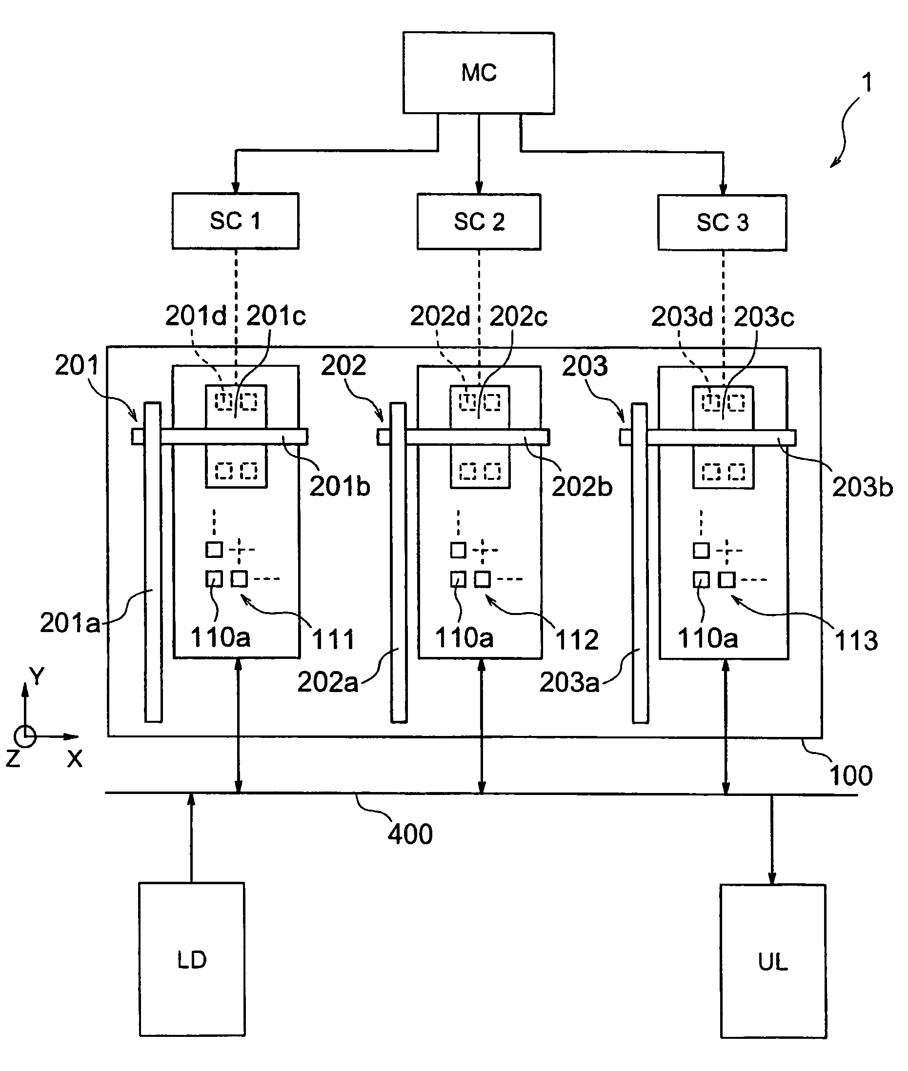
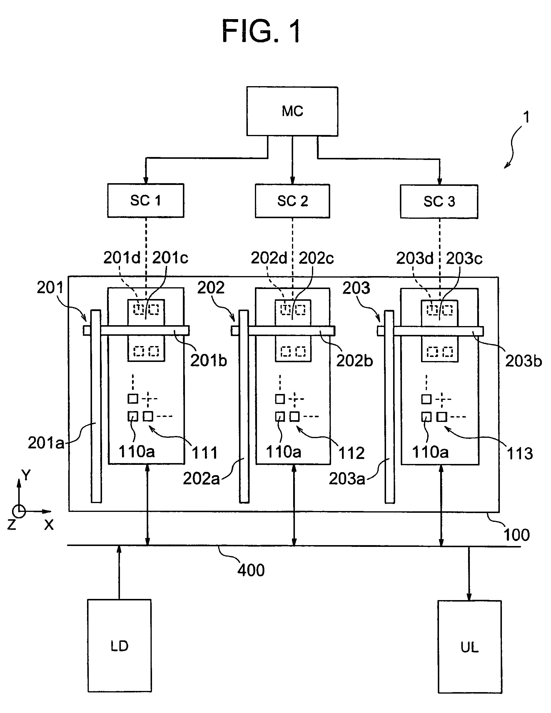
[0046]FIG. 1 is a view showing a schematic view showing an electronic device testing apparatus 1 in the first embodiment of the present invention and the control system.

[0047]The electronic device testing apparatus 1 of the present embodiment is an apparatus for conducting a test (inspection) of whether electronic devices 20 operate suitably in a state wherein the electronic devices to be tested 20 are applied with a thermal stress of a high temperature or low temperature, and classifying the electronic devices 20 in accordance with the test results; wherein an operation test in a state of applying such thermal stresses is conducted by conveying an electronic device conveying medium 10 loaded with the electronic devices 20 to be tested as test objects to the electronic device testing apparatus 1.

[0048]Therefore, the electronic devices testing apparatus 1 of the present embodiment comprises a loader section LD for supplying electronic device conveying medium 10 loaded with pre-test e...

second embodiment

[0175]In a test of an electronic device to be tested 20 on a wafer 701, test positions by the simultaneously measured number can be always secured in a few cases particularly in measurement near the outer circumference of the wafer 701, the situation is that only less test positions than the simultaneously measured number can be secured.

[0176]The present invention can be applied not only to the case of testing an electronic device conveying medium 10 of a strip-format, etc. described in the first embodiment, but to the case of testing electronic devices to be tested 20 on a wafer 701, and is advantageous to secure test positions by the simultaneously measured number.

[0177]As shown in FIG. 13, the test head portion 100 is composed of two prober groups: a first prober group 601 having 28 probers 600a and a second prober group 602 having 4 probers 600a. The simultaneously measured number in this case is 32. Among 72 electronic devices 20 to be tested on the seven lines on twelve rows o...


PUM


Abstract

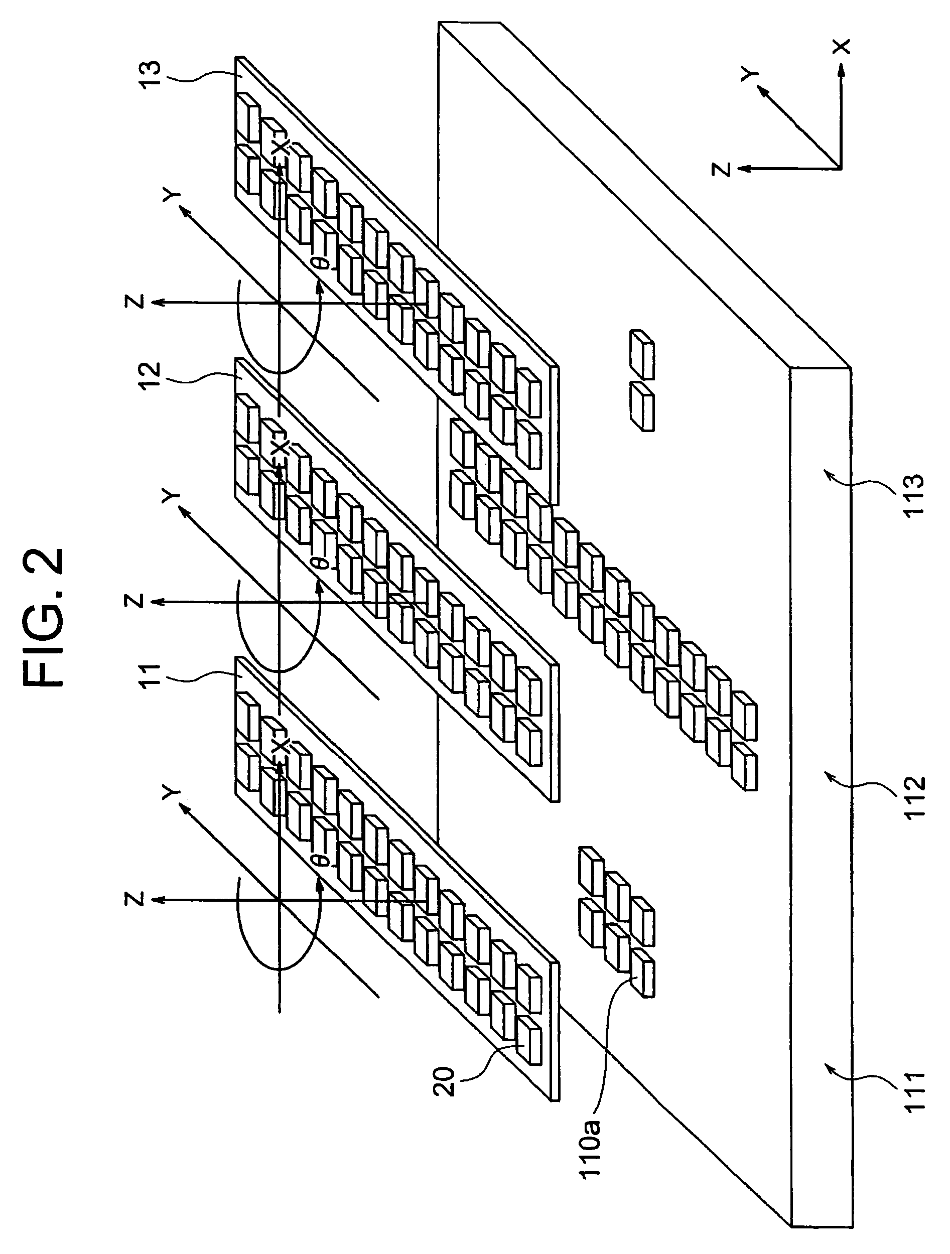
An electronic device testing apparatus for conducting a test by pressing input / output terminals of electronic devices to be tested (20) against contact portions (110a) of a test head (110) while holding the electronic devices to be tested (20) on electronic device conveying media (11, 12, 13): wherein the electronic device testing apparatus comprises a test head (100) provided with a plurality of contact groups (111, 112, 113) made by sets of contact portions (100a), and a plurality of moving means capable of controlling independently from each other; and the respective moving means move the electronic device conveying media (11, 12, 13) loaded with the electronic devices to be tested (20) to corresponding contact groups (111, 112, 113) to conduct a test.

Description

TECHNICAL FIELD[0001]The present invention relates to an electronic device testing apparatus for testing an electronic device, and an electronic device testing apparatus capable of conducting a test for any arrangement of electronic devices to be tested on an electronic device conveying medium with a high testing efficiency.BACKGROUND ART[0002]In an electronic device testing apparatus called a handler, a large number of electronic devices held on a tray are conveyed into the electronic device testing apparatus, and the respective electronic devices are brought to electronically contact a test head for conducting a test by an electronic device testing apparatus body (hereinafter, also referred to as a tester). When the test is finished, the electronic devices are taken out from the test head and reloaded to trays in accordance with the test results so as to be classified to categories of good ones and defective ones, etc.[0003]In conventional electronic device testing apparatuses, th...

Claims


Application Information

Patent Timeline
Patent Type & Authority Patents(United States)
IPC IPC(8): G01R31/28G01R31/02H01L21/66
CPCG01R31/2893G01R31/28
Inventor NAKAMURA, HIROTO
Owner ADVANTEST CORP
Learn More