Thermal vision mask

a technology of thermal vision mask and lcd display, which is applied in the direction of breathing protection, optical elements, instruments, etc., can solve the problem that the device under this patent does not utilize an infrared camera, and achieve the effect of greater ease of us

Inactive Publication Date: 2008-12-02
EPSTEIN JAY F +1
View PDF11 Cites 39 Cited by
  • Summary
  • Abstract
  • Description
  • Claims
  • Application Information

AI Technical Summary

Benefits of technology

[0015]The invention is a thermal imaging camera lens that has an LCD display mounted on the opposing side of the camera, which is integrated into a fire mask visor. The fire mask visor is used in conjunction with an oxygen mask. The thermal imaging lens is directed along the same line of sight as the user's, which provides for greater ease of use in hazardous situations.

Problems solved by technology

However, the thermal imaging device is mounted on the helmet and requires a display to be angled down to the user's eyesight, as opposed to a thermal imaging lens that has an LCD screen on the backside of which it is mounted to the actual visor.
However, this device wraps around the head or helmet of the end user as opposed to mounting to the visor of an oxygen delivery mask.
Furthermore, the device under this patent does not utilize an infrared camera that is mounted to the opposite side of the LCD display screen.

Method used


Image

  • Thermal vision mask
  • Thermal vision mask
  • Thermal vision mask

Examples


Embodiment Construction

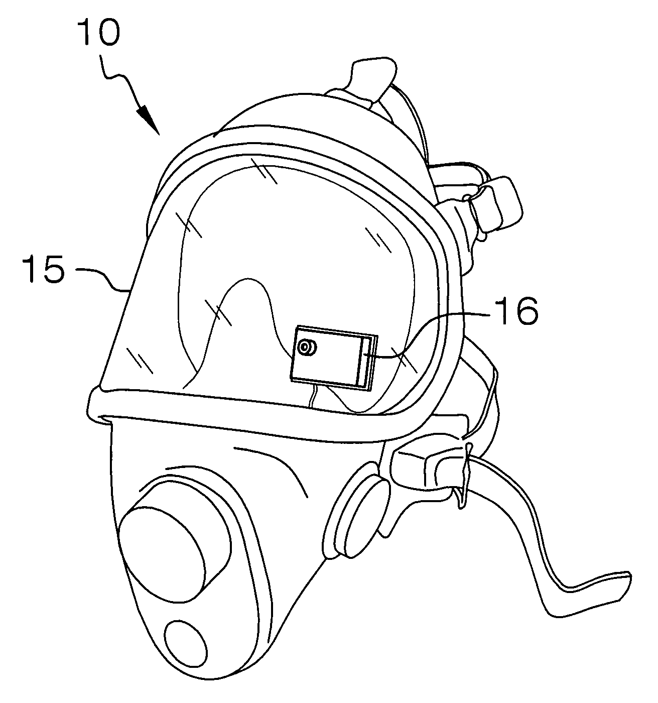
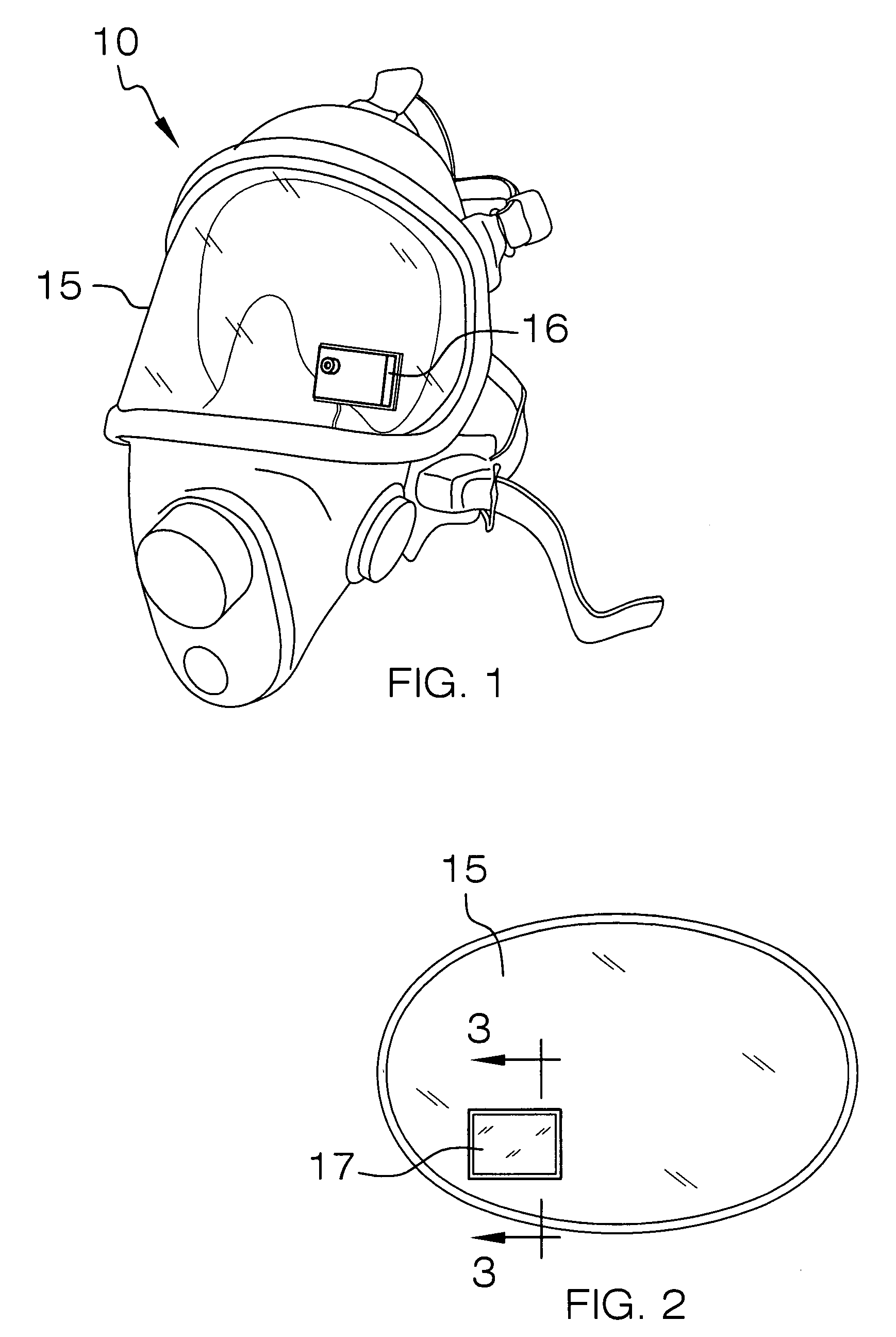
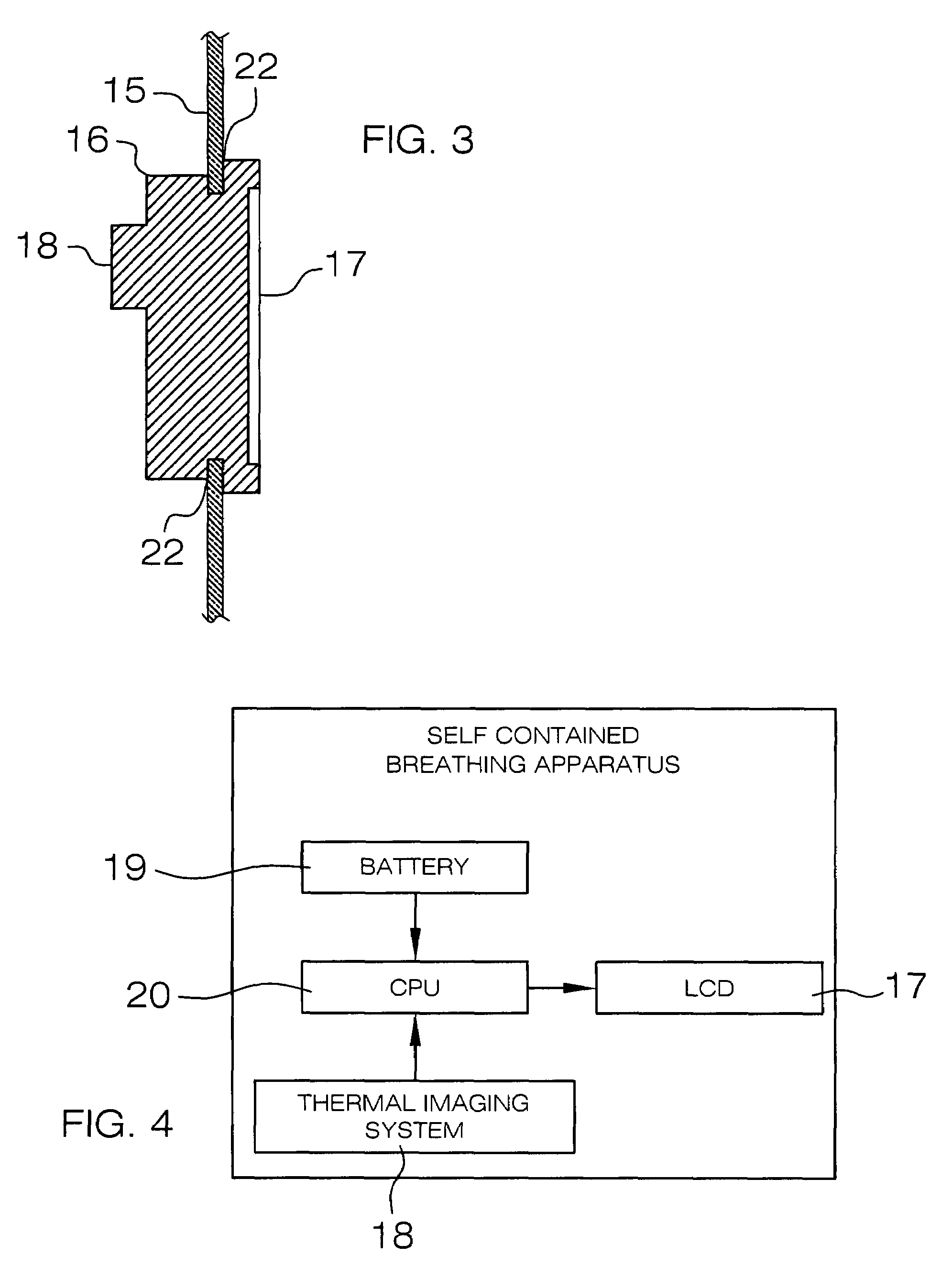
[0023]Detailed reference will now be made to the preferred embodiment of the present invention, examples of which are illustrated in FIGS. 1-5. An invention 10 comprises a visor 15 that has an opening to accommodate a thermal imaging system housing 16. The thermal imaging system housing 16 has a small LCD display 17, and a thermal imaging lens 18. Located within the thermal imaging system housing 16 is a battery supply 19, and a central processing unit (hereinafter CPU) 20. It is further asserted that the direction of the thermal imaging lens 18 can be adjusted to the desired angle of the end user. The range of direction of the thermal imaging lens 18 is + / −30 degrees in a swivel-like configuration.

[0024]The thermal imaging lens 18 generates a signal, which is transferred to the CPU 20. The CPU 20 then processes the signal, and transfers the signal to the LCD display 17. The LCD display 17 then projects the image onto its display.

[0025]The thermal imaging system housing 16 has a not...


PUM


Abstract

The invention is a thermal imaging camera lens that has an LCD display mounted on the opposing side of the camera, which is integrated into a fire mask visor. The fire mask visor is used in conjunction with an oxygen mask. The thermal imaging lens is directed along the same line of sight as the user's, which provides for greater ease of use in hazardous situations. However, the thermal imaging lens can be rotated to a desired angle and line of sight of the end user. A sealant can be applied to the perimeter of the thermal imaging system housing and the visor to prevent the introduction of smoke and/or hazardous gases from entering the interior side of the visor.

Description

CROSS REFERENCES TO RELATED APPLICATIONS[0001]Not ApplicableSTATEMENT REGARDING FEDERALLY SPONSORED RESEARCH[0002]Not ApplicableREFERENCE TO APPENDIX[0003]Not ApplicableBACKGROUND OF THE INVENTION[0004]A. Field of the Invention[0005]The present invention relates to a thermal camera and LCD display arrangement and more specifically to the application of said invention to the surface of a visor when used in conjunction with an oxygen supply mask.[0006]Thermal imaging devices have found particularly useful in firefighting and search and rescue operations as they enable the end user to see through the dark or thick smoke.[0007]B. Discussion of the Prior Art[0008]The Olita et al. Patent Application Publication (U.S. Pub. No. 2003 / 0122958) discloses a fire fighter's helmet which has a thermal imaging system mounted thereon. However, the thermal imaging device is mounted on the helmet and requires a display to be angled down to the user's eyesight, as opposed to a thermal imaging lens that...

Claims


Application Information

Patent Timeline
Patent Type & Authority Patents(United States)
IPC IPC(8): G02B27/10
CPCA62B18/082G02B23/125G02B27/017G02B2027/0138
Inventor EPSTEIN, JAY F.EPSTEIN, HALIE
Owner EPSTEIN JAY F
Why Eureka
Try Eureka