Transmitting apparatus of communication system

a technology of communication system and transmitting apparatus, applied in the field of transmitting apparatus, can solve the problems of reducing system resolution, affecting the accuracy of channel measurement, and channel value distortion, so as to facilitate accurate radio channel measurement, increase the operation burden of the transmitting apparatus, and measure the radio channel accurately.

Inactive Publication Date: 2008-12-02
ELECTRONICS & TELECOMM RES INST
View PDF2 Cites 2 Cited by
  • Summary
  • Abstract
  • Description
  • Claims
  • Application Information

AI Technical Summary

Benefits of technology

[0018]In more detail, the advantage of the present invention is to provide a transmitting apparatus for enabling accurate radio channel measurement without an increase of operation burden of a receiving apparatus by compensating an original characteristic of a communication system.
[0019]An exemplary transmitting apparatus according to an embodiment of the present invention is for enabling a receiving apparatus to measure a radio channel accurately. The transmitting apparatus includes a code generator, a modulator, a pulse shaper, an analogue filtering and amplifying unit, and a prefilter.
[0020]The code generator diffuses a signal to be transmitted by a pseudo-noise (PN) code. The modulator modulates the diffused signal. The pulse shaper pulse-shapes the modulated signal. The analogue filtering and amplifying unit filters and amplifies the pulse-shaped signal. The prefilter compensates a previously measured estimated impulse response of the communication system by assuming a communication system in which the transmitting apparatus and the receiving apparatus are directly connected. Another exemplary transmitting apparatus according to another embodiment of the present invention is for enabling a receiving apparatus to measure a radio channel accurately. The transmitting apparatus includes a pseudo-noise (PN) code generator, a modulator, a pulse shaper, and an analogue filtering and amplifying unit. The pseudo-noise (PN) code generator prefilters and diffuses a signal to be transmitted by the PN code in which a compensated value of an impulse response of the communication system is stored after assuming a communication system in which the transmitting apparatus and the receiving apparatus are directly connected. The modulator modulates the prefiltered and diffused signal. The pulse shaper pulse-shapes the modulated signal. The analogue filtering and amplifying unit filters and amplifies the pulse-shaped signal and transmits the signal to the receiving apparatus.

Problems solved by technology

The original characteristic of the communication system interferes with accurate channel measurement.
In more detail, it causes a distortion of channel value and a reduction of system resolution.
This method cannot compensate the original characteristic of the communication system, but compensates a channel measurement error caused by a characteristic of PN code (refer to T. Korhonen and S-G.
The prior arts mentioned above have drawbacks in that they cannot provided accurate measurement of a channel because they reduce system performance by amplifying noise, and they cannot compensate the original characteristic of the communication system.
In addition, an operation burden is increased because compensation of the receiver 300 needs to be performed on the received signal.

Method used


Image

  • Transmitting apparatus of communication system
  • Transmitting apparatus of communication system
  • Transmitting apparatus of communication system

Examples


Embodiment Construction

[0025]An embodiment of the present invention will hereinafter be described in detail with reference to the accompanying drawings.

[0026]In the following detailed description, only certain exemplary embodiments of the present invention have been shown and described, simply by way of illustration. As those skilled in the art would realize, the described embodiments may be modified in various different ways, all without departing from the spirit or scope of the present invention. Accordingly, the drawings and description are to be regarded as illustrative in nature and not restrictive. Like reference numerals designate like elements throughout the specification.

[0027]Hereinafter, a transmitting apparatus of a communication system according to an exemplary embodiment of the present invention will be described in detail.

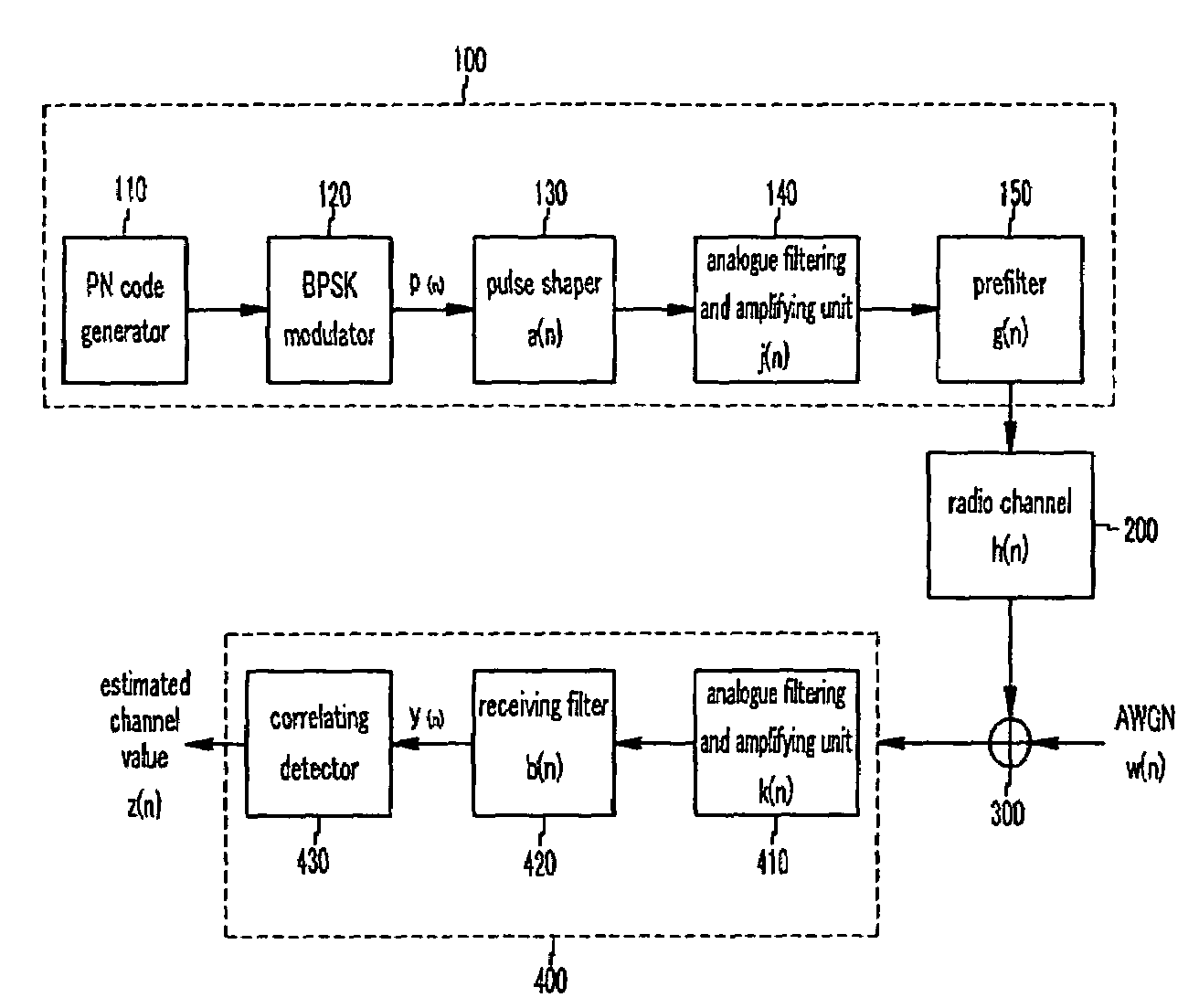
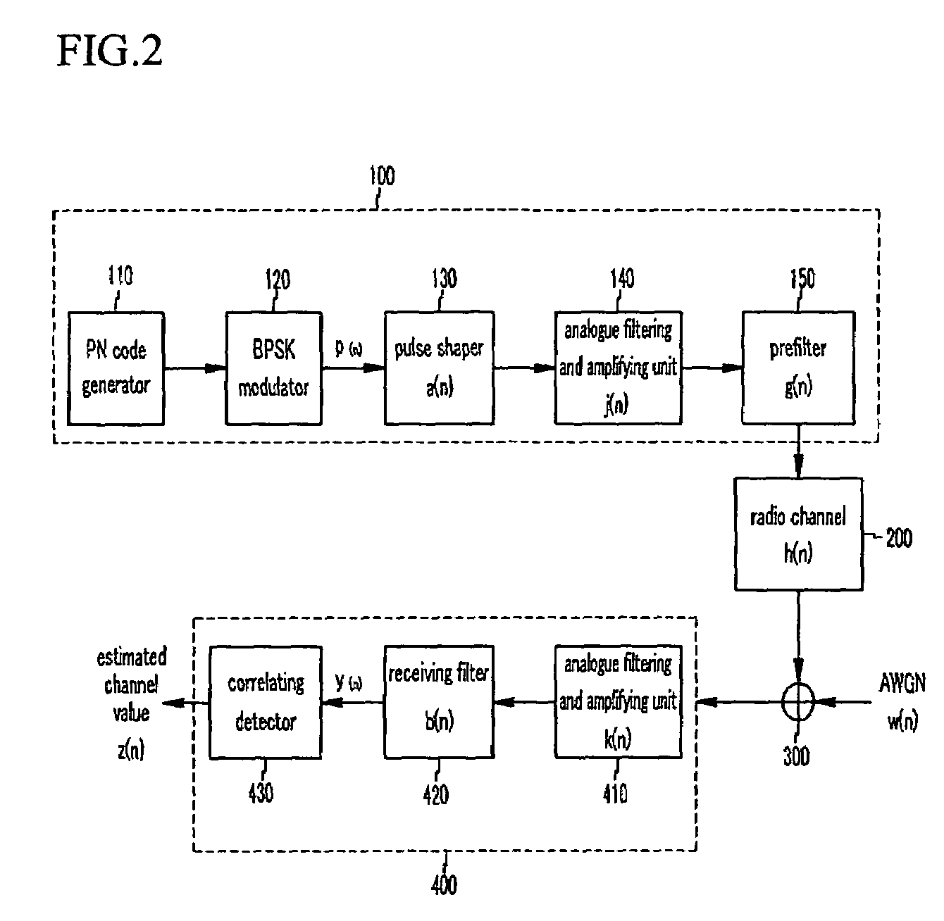
[0028]FIG. 2 shows a communication system according to the first exemplary embodiment of the present invention.

[0029]As shown in FIG. 2, the communication system includes ...


PUM


Abstract

A transmitting apparatus according to the present invention includes a prefilter for compensating a previously measured estimated impulse response of a communication system by assuming a communication system in which the transmitting apparatus and the receiving apparatus are directly connected. The prefilter included in the transmitting apparatus compensates an original characteristic of a communication system. Accordingly, the prefilter enables an accurate channel measurement of a receiving apparatus without any increase of calculation.

Description

CROSS-REFERENCE TO RELATED APPLICATION[0001]This application claims priority to and the benefit of Korean Patent Application 10-2004-0084755 and 10-2005-0033114 respectively filed in the Korean Intellectual Property Office on Oct. 22, 2004 and Apr. 21, 2005, the entire contents of which are incorporated herein by reference.BACKGROUND OF THE INVENTION[0002](a) Field of the Invention[0003]The present invention relates to a communication system. More particularly, the present invention relates to a transmitting apparatus for enabling a receiving apparatus to measure a radio channel with increased accuracy in a communication system.[0004](b) Description of the Related Art[0005]Generally, a communication system can operate properly when the system is designed to be suitable for a channel to be used. Therefore, it is important to understand characteristics of a channel used in the communication system in order to design the system.[0006]The next generation wireless communication system ne...

Claims


Application Information

Patent Timeline
Patent Type & Authority Patents(United States)
IPC IPC(8): H04Q7/00H04B1/707H04B1/711H04B3/04
CPCH04B17/21H04L25/0288
Inventor LEE, HONG-SUPCHUNG, HYUN-KYULEE, KWANG-CHUN
Owner ELECTRONICS & TELECOMM RES INST
Why Eureka
Try Eureka