Gas turbine electric powerplant

a technology of electric power plants and gas turbines, applied in the direction of engine cooling devices, air transportation, engine fuctions, etc., can solve the problems of large industrial facilities limited in the amount of power they may use, high price, and high general consumption of electric power

Inactive Publication Date: 2008-12-09
ALTEK POWER CORP
View PDF40 Cites 24 Cited by
  • Summary
  • Abstract
  • Description
  • Claims
  • Application Information

AI Technical Summary

Benefits of technology

[0008]The control system of the gas turbine electric powerplant of the present invention can provide for automatic start-up and operation when high demand is detected. When the demand ebbs, the gas turbine electric powerplants can be shut down as needed. The portability of the gas turbine electric powerplant of the present invention also allows additional units to be set up at a utility if needed to meet increasing peak demand. Such a situation may occur when a particular area or areas served by a utility grows at a faster than expected rate. In this manner, both the cost of building a power generating plant and the cost of producing electricity may be reduced, while still ensuring that peak demand can be met.
[0009]The gas turbine electric powerplant of the present invention can also be used as a source of co-generation electric power. For example, the gas turbine electric powerplant may be installed at an industrial facility and tied into the facility's electric power transmission and distribution system in order to augment the electric power supplied by an electric utility company. The cost to purchase electric power from a utility may vary throughout a given day or week. For example, it is common for large industrial facilities to be limited in the amount of power they may use, or to otherwise be charged a significantly elevated price during periods of high demand. Such may occur, for example, during periods of extreme weather, when the general consumption of electric power typically increases. When such a situation exists, the industrial facility may operate one or more of the gas turbine electric powerplants to supplement the electric power it receives from the utility. In this manner, the industrial facility can avoid having to either reduce its power consumption or pay a higher cost for electric power during such periods.
[0010]The gas turbine electric powerplant of the present invention can also be used as a source of distributed power generation. As certain populated areas grow, the demand for electric power generally increases. Many times, the provider of electric power does not have the capacity to meet the increased demand. Electric utilities often form cooperatives, or otherwise enter into agreements wherein electric power may be sold and delivered between the utilities. Thus, if one utility cannot meet demand, and a second utility has excess capacity, the second utility may sell blocks of power to the first utility. The first utility may be at a disadvantage, because the cost to purchase and transfer the electric power to the area of demand may be high. The second utility is able to take advantage of its excess capacity by selling and distributing the electricity to other providers. The gas turbine electric powerplant of the present invention can be used to take advantage of growing markets, by allowing a provider to produce additional electric power that may be sold to other providers without sufficient capacity. Alternatively, the gas turbine electric powerplant of the present invention may be used by a provider to obviate the need for purchasing additional electric power from another utility. Rather, the provider may use the gas turbine electric powerplant to produce incremental electric power in small blocks, minimizing large incremental power block purchases from other utilities. The gas turbine electric powerplant can be located to provide electric power wherever it is needed. For example, the gas turbine electric powerplant may be placed at a distribution substation and tied into a utility's transmission and distribution lines.
[0015]The gas turbine electric powerplant is designed to operate on both liquid and gaseous fuels that can provide a sufficient BTU output. Specific microprocessor-controlled fuel valves are provided based on the type of fuel that will be used to run the gas turbine electric powerplant. The fuel valves may be changed if it is desired to change the type of fuel used with the gas turbine electric powerplant. The microprocessor-based design of each type of fuel valve allows the valve to communicate with and respond to instructions from the microprocessor-based control system.
[0016]The assembled components of the gas turbine electric powerplant reside on a common base, preferably on a transportable skid. A specialized frame is mounted to the skid and designed to receive and restrain the turbine engine. The frame is designed to maintain the centerline of the turbine engine despite the thermal expansion thereof. The size and weight of the gas turbine electric powerplant components and skid allow it to be transported by truck to virtually any site where electric power is needed. Therefore, the gas turbine electric powerplant of the present invention provides for a portable source of significant electric power production that may be utilized to meet a number of consumer needs.

Problems solved by technology

For example, it is common for large industrial facilities to be limited in the amount of power they may use, or to otherwise be charged a significantly elevated price during periods of high demand.
Such may occur, for example, during periods of extreme weather, when the general consumption of electric power typically increases.
Many times, the provider of electric power does not have the capacity to meet the increased demand.
The first utility may be at a disadvantage, because the cost to purchase and transfer the electric power to the area of demand may be high.

Method used


Image

  • Gas turbine electric powerplant
  • Gas turbine electric powerplant
  • Gas turbine electric powerplant

Examples


Embodiment Construction

)

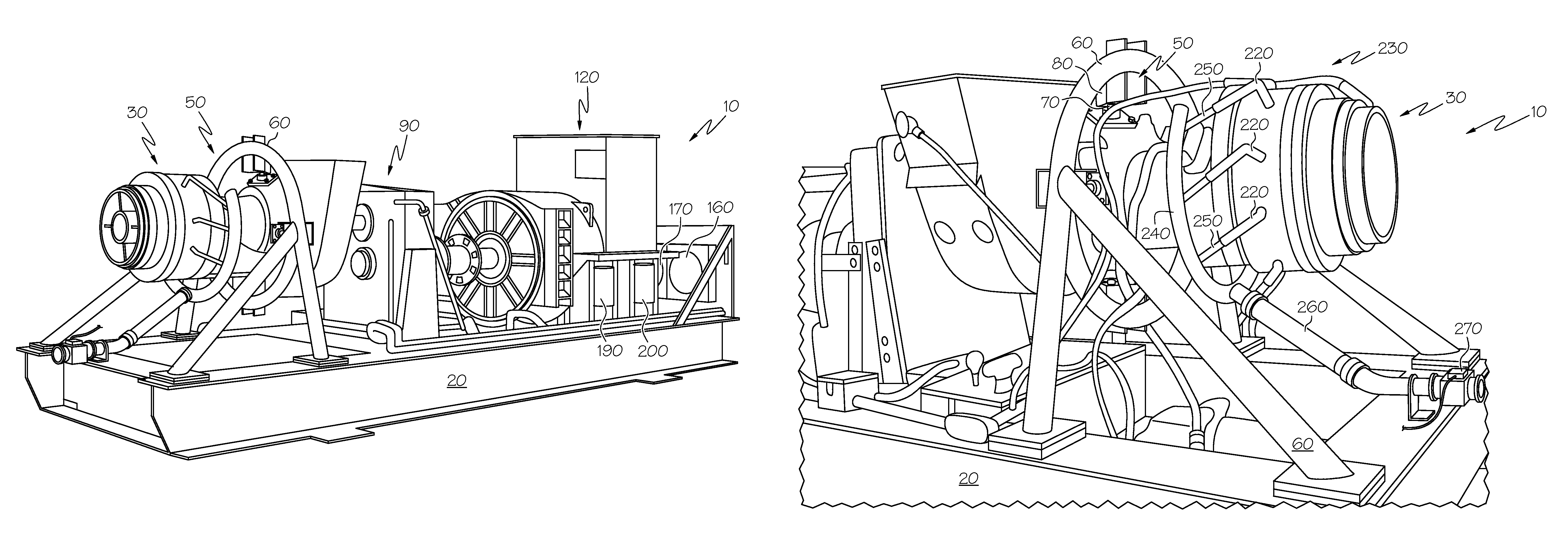
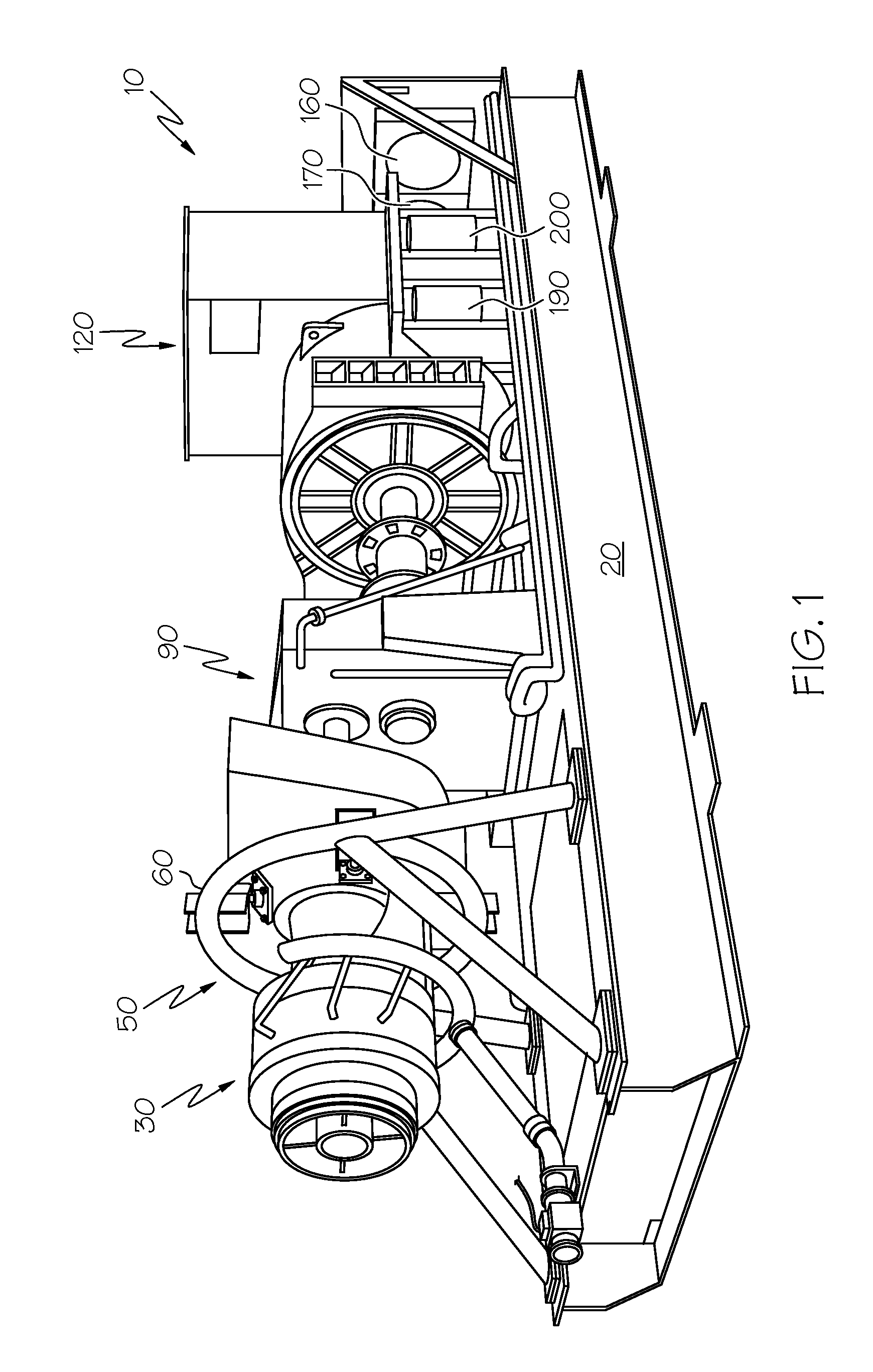
[0030]An isometric view of one embodiment of a gas turbine electric powerplant 10 of the present invention can be observed in FIG. 1. The gas turbine electric powerplant 10 preferably resides on a unitary base, such as the skid 20 shown. In this manner, the entire gas turbine electric powerplant 10 can be easily and conveniently transported to virtually any location requiring electric power production. It is also possible, however, to assemble the gas turbine electric powerplant 10 onto a fixed mounting surface, such as, for example, the floor of a factory.

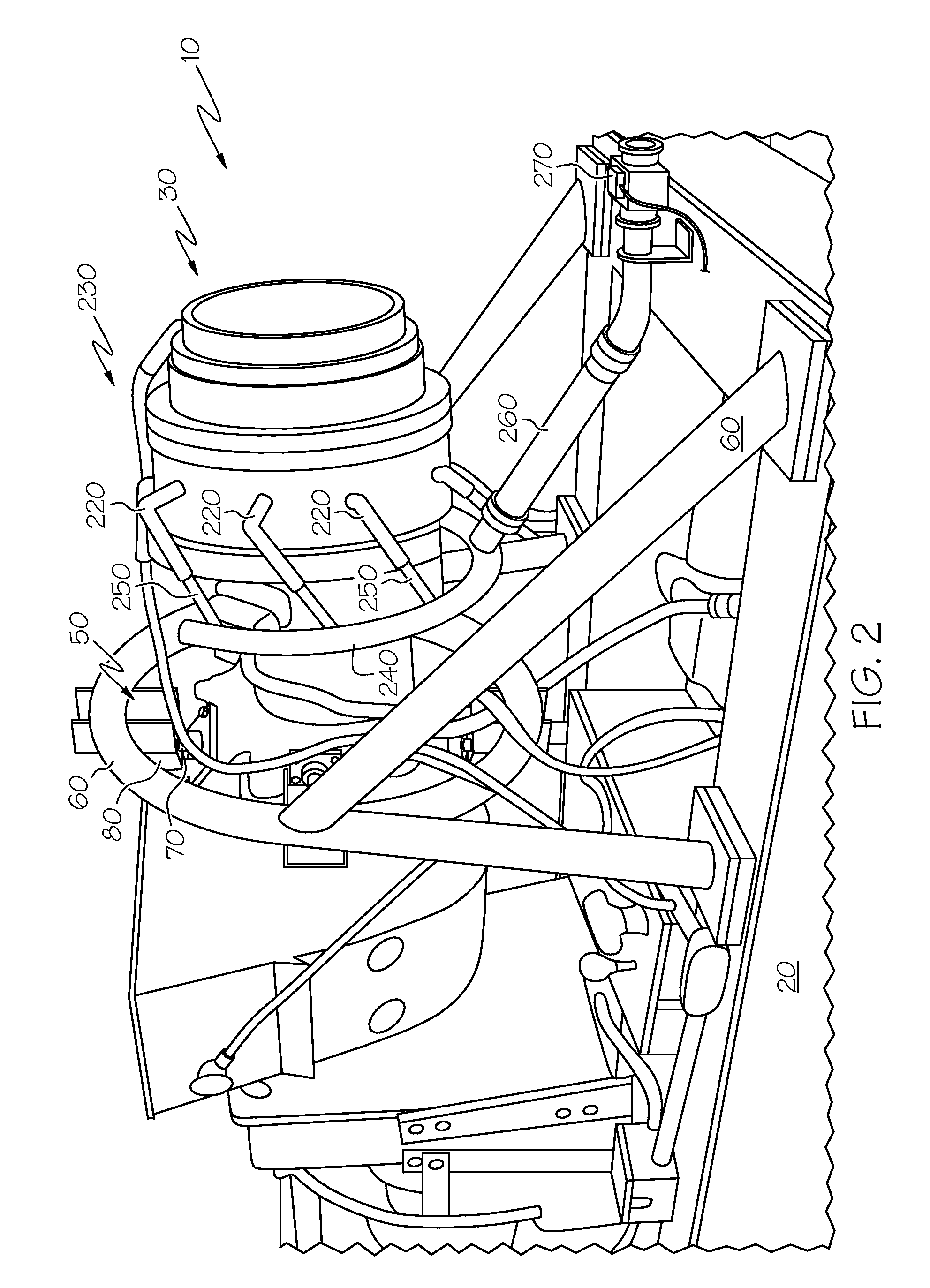
[0031]The gas turbine electric powerplant 10 is shown to be powered by a turbine engine 30, which can be better observed by reference to FIG. 2. The turbine engine 30 may be aeroderivative, such as is intended for use in a helicopter or other aircraft. Preferably, the turbine engine 30 is a turboshaft engine, wherein an output shaft connected to a turbine within the engine is provided for coupling to an external device. The use o...


PUM


Abstract

A gas turbine electric powerplant, preferably driven by an aeroderivative turbine engine of split shaft design. The gas turbine engine is coupled to a speed reducer, which is in turn coupled to an electric generator. An engine mount is provided that ensures that the gas turbine engine will remain in proper alignment with the speed reducer and generator, even during the thermal expansion or contraction thereof. Preferably, the components comprising the powerplant are mounted to a common, transportable base, so that the powerplant can be delivered to various locations. An overspeed control system is provided for ensuring that a runaway condition of the gas turbine engine does not occur should the gas turbine engine become disconnected from the speed reducer or generator. Sensors are used to monitor multiple operating conditions of the powerplant. A microprocessor-based control system communicates with the sensors, and is further adapted to activate the overspeed control system if an overspeed condition is detected.

Description

[0001]This application is a continuation of U.S. patent application Ser. No. 10,123,123, filed on Apr. 16, 2002.BACKGROUND OF THE INVENTION[0002]The present invention relates to a gas turbine electric powerplant. The gas turbine electric powerplant uses a turbine engine, such as an aircraft engine, to operate an electric generator that produces electric power. The gas turbine electric powerplant can be portable, and may be easily transported to virtually any location where electric power generation is needed. The gas turbine electric powerplant is also adapted to allow safe, unattended operation.[0003]There are numerous situations wherein it may be desirable to use a gas turbine electric powerplant of the present invention. For example, it may be necessary to provide electric power to a remote area that is not supplied by a utility company. Electric power consuming operations that are commonly conducted in remote areas include, for example, drilling for oil and natural gas. Such ope...

Claims


Application Information

Patent Timeline
Patent Type & Authority Patents(United States)
IPC IPC(8): F02C7/20
CPCF01D15/10F01D15/12F01D21/02F01D25/28F02C7/12F02C7/20Y02T50/675F05D2270/021F05D2260/20Y02T50/60
Inventor MUNSON, JR., BILL C.
Owner ALTEK POWER CORP
Why Eureka
Try Eureka