Device for connection between a rail for fuel under pressure and at least one injector, for an internal-combustion engine

a technology of injectors and rails, which is applied in the direction of liquid fuel feeders, machines/engines, mechanical apparatus, etc., can solve the problems of structural criticality, relatively heavy and costly injection systems, and placement of engines, and achieves the effect of limited cost and high reliability

Active Publication Date: 2008-12-09
CENT RICERCHE FIAT SCPA
View PDF20 Cites 15 Cited by
  • Summary
  • Abstract
  • Description
  • Claims
  • Application Information

AI Technical Summary

Benefits of technology

[0009]The aim of the invention is to provide a device for connection between a fuel rail and a set of injectors for an internal-combustion engine, which will present high reliability and limited cost, eliminating the drawbacks of the connection devices of the known art.

Problems solved by technology

Both this plate and the rail require a considerable space in the engine compartment, so that their placing on the engine is rather complicated, and the injection system proves relatively heavy and costly.
On account of the high operating pressures, said fit consequently proves structurally critical.
In addition, since the swelling of the tube is in direct contact with the rail, without any intermediate connection, it is not possible to set, between the rail itself and each tube, a calibrated restriction for hydraulically uncoupling the tube from the rail.
The direct seal of the swelling of the tube on the rail penalizes the flexibility of the system, so that any even slight misalignment of the axis of the tube with respect to the axis of the conical seat of the rail, for example due to normal activities of maintenance of the engine, could jeopardize its tightness.
Consequently, should the two elements be uncoupled, it would no longer be possible to guarantee tightness in the subsequent assembly.

Method used


Image

  • Device for connection between a rail for fuel under pressure and at least one injector, for an internal-combustion engine
  • Device for connection between a rail for fuel under pressure and at least one injector, for an internal-combustion engine
  • Device for connection between a rail for fuel under pressure and at least one injector, for an internal-combustion engine

Examples


Embodiment Construction

[0020]Further scope of applicability of the present invention will become apparent from the detailed description given hereinafter. However, it should be understood that the detailed description and specific examples, while indicating preferred embodiments of the invention, are given by way of illustration only, since various changes and modifications within the spirit and scope of the invention will become apparent to those skilled in the art from this detailed description.

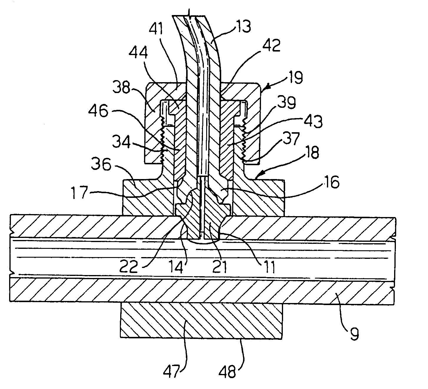
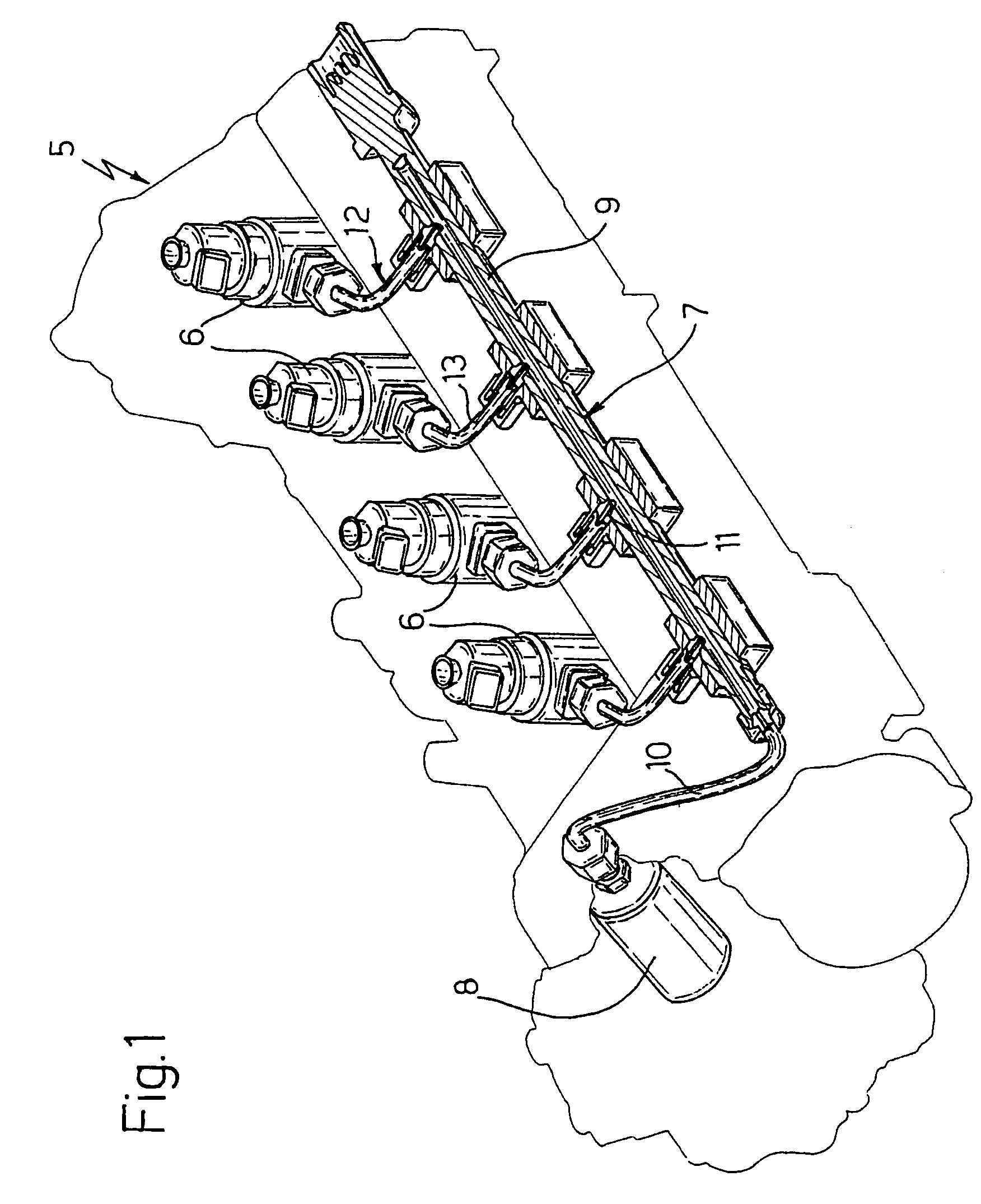
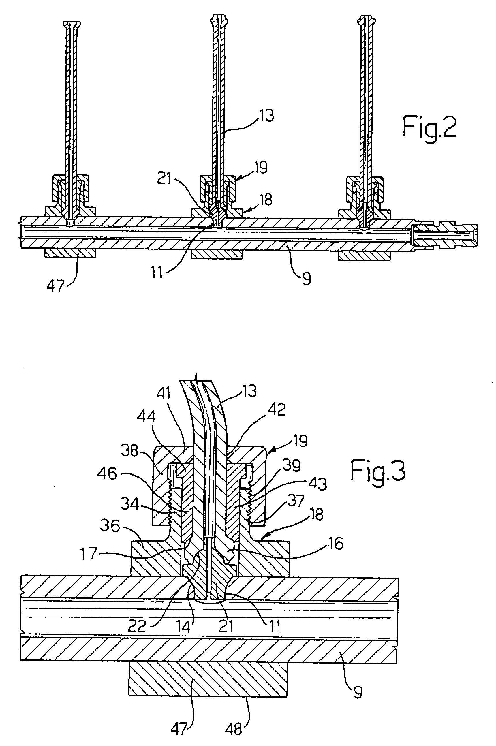
[0021]With reference to FIG. 1, number 5 designates as a whole an internal-combustion engine, for example a four-cylinder diesel-cycle engine. The engine 5 is equipped with four injectors 6 associated to the cylinders, which are supplied by a common rail 7 for fuel under pressure, supplied by a high-pressure pump 8. The rail 7 has a hollow body 9 substantially of a cylindrical shape, and is connected to the pump 8 via a high-pressure duct 10.

[0022]The rail 7 is provided with a series of radial holes 11 associated...


PUM


Abstract

The device includes a connection tube in communication with a hole of a rail for fuel under pressure, the tube being provided with an end swelling. The device has a first threaded element fixed to the rail in a position corresponding to the hole and a second threaded element designed to engage the first threaded element. Removably set between the hole and the swelling is a seal element designed to form a seal both with the hole and with the swelling. The seal element is a body of revolution equipped with a passage along a pre-set axis, and includes two end noses designed to be inserted in the swelling and in the hole, respectively, and two tapered seal stretches.

Description

BACKGROUND OF THE INVENTION[0001]1. Field of the Invention[0002]The present invention relates to a device for connection between a rail for fuel under pressure and at least one injector, for an internal-combustion engine.[0003]2. Description of the Related Art[0004]As is known, in injection engines the rail for fuel under pressure, common for all the injectors, is connected to the injectors themselves by means of metal tubes. The rail has a tubular shape and has an external diameter in the region of 30 mm, an internal diameter in the region of 10 mm, and a weight of approximately 3 kg. The tubes are normally connected to the rail by welding and have the only function of hydraulic connection. In turn, the rail is fixed on the engine block by means of an appropriate supporting plate. Both this plate and the rail require a considerable space in the engine compartment, so that their placing on the engine is rather complicated, and the injection system proves relatively heavy and costly....

Claims


Application Information

Patent Timeline
Patent Type & Authority Patents(United States)
IPC IPC(8): F02M55/02F02M69/46
CPCF02M55/005F02M55/025
Inventor RICCO, MARIODE MATTHAEIS, SISTO LUIGIRICCO, RAFFAELEDI MEO, ALFONSO
Owner CENT RICERCHE FIAT SCPA
Why Eureka
Try Eureka