Directional drilling control

a directional drilling and control technology, applied in the direction of vibration drilling, vibration device, borehole/well accessories, etc., can solve the problems of difficult to overcome friction, difficult for the driller to apply sufficient weight to the bit to achieve an optimal penetration rate, and the weight of the drill bit tends to overshoot the optimum magnitude, so as to reduce the sliding friction of the drillstring and move the bit efficiently and effectively through the formation.

Active Publication Date: 2008-12-09
VARCO I P INC
View PDF38 Cites 34 Cited by
  • Summary
  • Abstract
  • Description
  • Claims
  • Application Information

AI Technical Summary

Benefits of technology

[0011]The present invention discloses, in certain aspects, systems and methods for moving a bit efficiently and effectively through a formation while inhibiting or preventing binding of the drillstring on the formation and maintaining a desired bit face orientation during drilling. In certain aspects, such systems and methods reduce sliding friction of the drillstring with respect to the formation.
[0013]In certain embodiments of the present invention a system is provided for moving a drill string, particular non-vertical portions of a drillstring, through a formation by imparting a certain desired amount of energy to the string with a top drive motor, with a rotary table, or with a power swivel to rotate the string in a first direction and then imparting a certain desired amount of energy to the string to rotate it in an opposite second direction, thereby reducing sliding friction of the string and binding of the string on the formation. As needed, continuous oscillation in one direction then the other is repeated.
[0017]It is, therefore, an object of at least certain preferred embodiments of the present invention to provide new, useful, unique, efficient, nonobvious systems and methods, including, but not limited to: systems and methods for imparting specified amounts of energy to a drillstring and / or for oscillating a drillstring, first in one direction then in an opposite direction; in certain aspects to reduce binding against a formation and / or to reduce sliding friction.

Problems solved by technology

Since the drillstring is not rotating, it is difficult to overcome the friction.
The difficulty in overcoming the friction makes it difficult for the driller to apply sufficient weight to the bit to achieve an optimal rate of penetration.
The drillstring exhibits stick / slip friction such that when a sufficient amount of weight is applied to overcome the friction, the drill the weight on bit tends to overshoot the optimum magnitude.
Moreover, in certain methods when the driller applies drillstring angle corrections at the surface in an attempt to correct the bit face angle, a substantial amount of the angular change is absorbed by friction without changing the face angle in stick / slip fashion.
One of the challenges for directional drilling is preventing the horizontal portions of the string from binding with the surrounding rock formation and reducing sliding friction as the bit progresses through the formation.
In rotating a drillstring to overcome undesirable sticking and friction, ideally such rotation does not change the bit face orientation; but, due to the limitations of available prior art systems and methods, it is often difficult to nullify frictional effects on the drillstring without adversely changing bit face orientation.

Method used


Image

  • Directional drilling control
  • Directional drilling control
  • Directional drilling control

Examples


Embodiment Construction

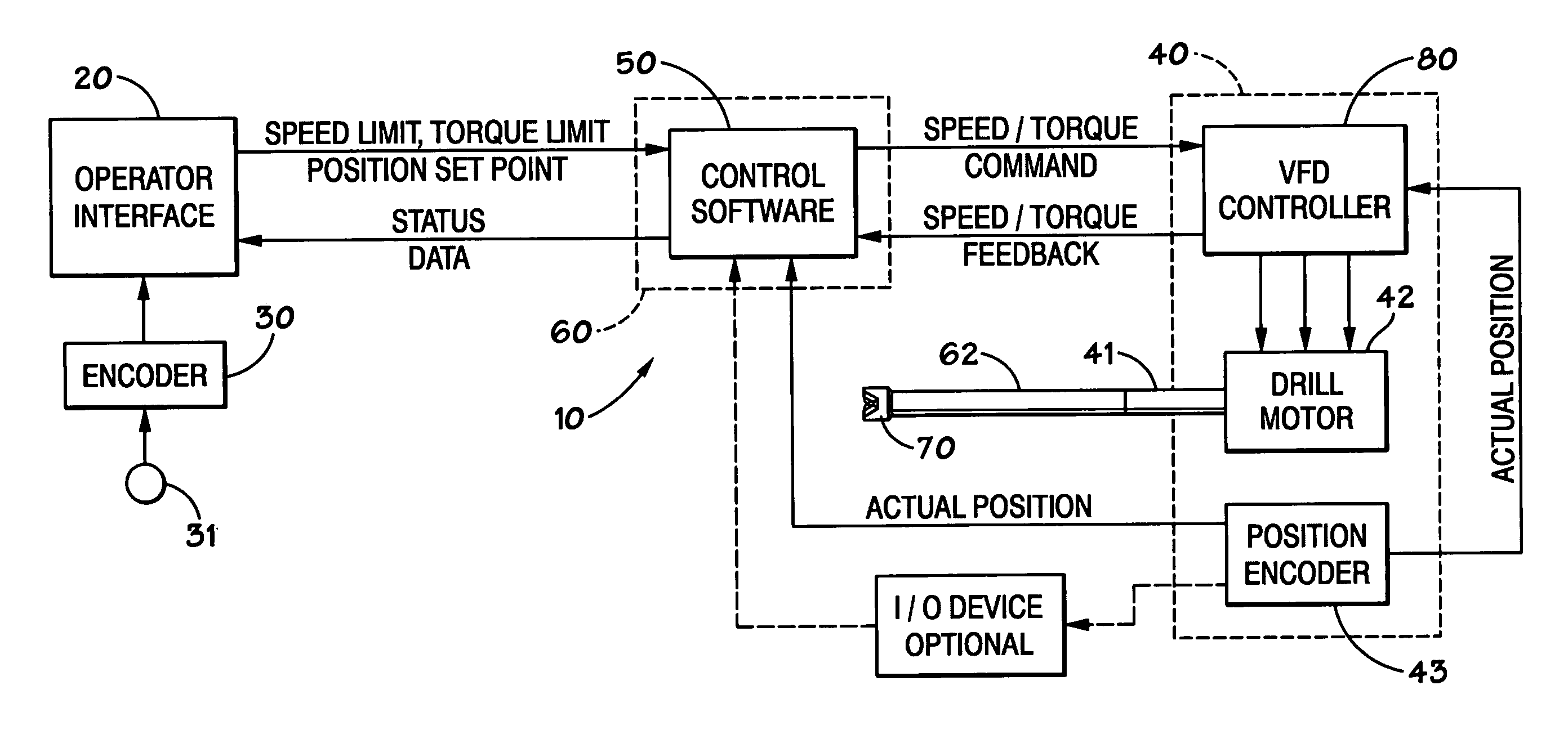
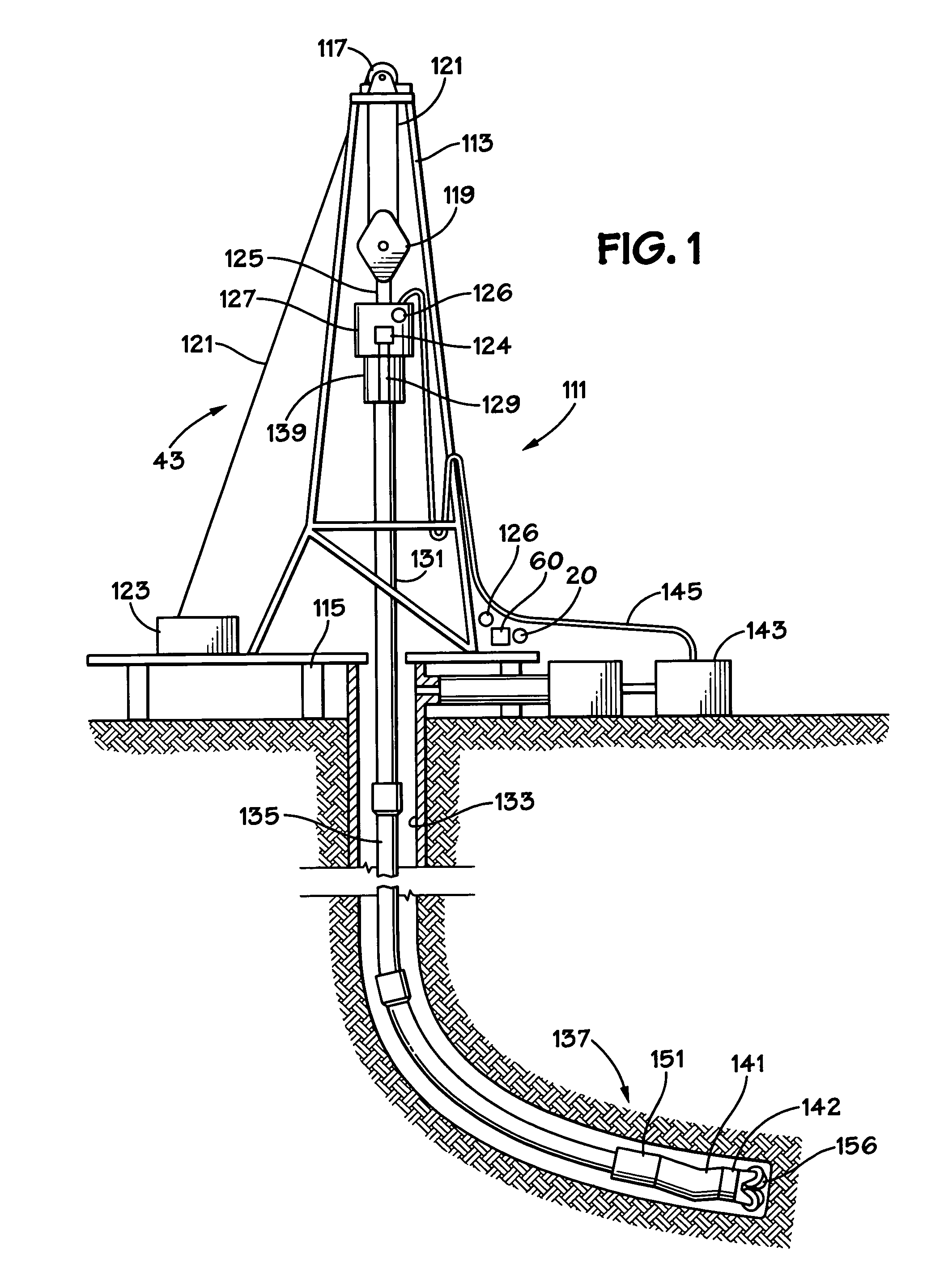
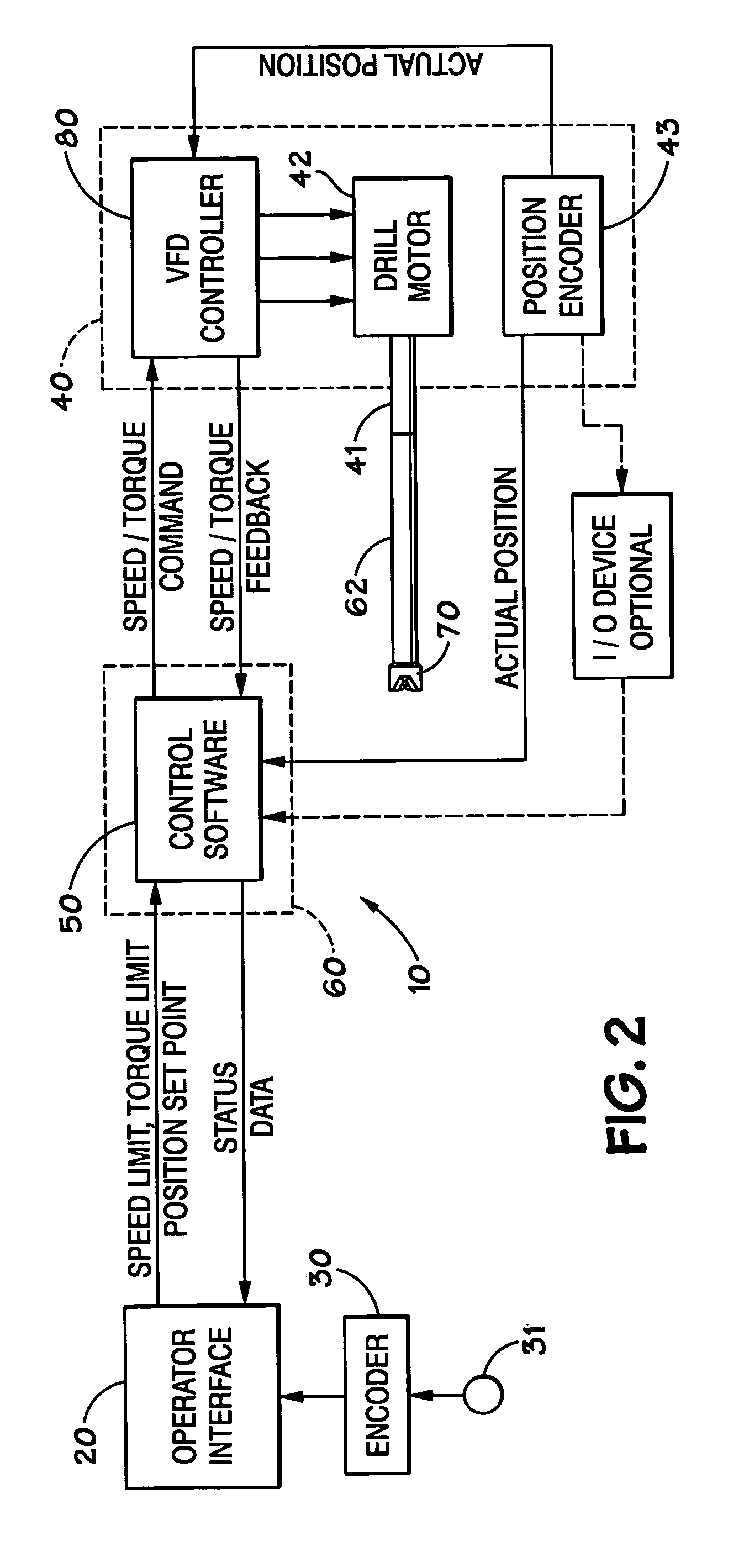
[0027]Referring now to FIG. 1, a drilling rig 111 is depicted schematically as a land rig, but other rigs (e.g., offshore rigs, jack-up rigs, semisubmersibles, drill ships, and the like) are within the scope of the present invention. In conjunction with an operator interface, e.g. an interface 20, a control system 60 as described below controls certain operations of the rig. The rig 111 includes a derrick 113 that is supported on the ground above a rig floor 115. The rig 111 includes lifting gear, which includes a crown block 117 mounted to derrick 113 and a traveling block 119. A crown block 117 and a traveling block 119 are interconnected by a cable 121 that is driven by drawworks 123 to control the upward and downward movement of the traveling block 119. Traveling block 119 carries a hook 125 from which is suspended a top drive system 127 which includes a variable frequency drive controller 126, a motor (or motors) 124 and a drive shaft 129. The top drive system 127 rotates a dri...


PUM


Abstract

A method for oscillating a drillstring, the drillstring extending into the earth, the drillstring having a bit on a lower end thereof, the bit for drilling into the earth, the drillstring connected to a motive apparatus, the motive apparatus for rotating the drillstring, the motive apparatus having a power output associated with rotating the drillstring, the method including, in certain aspects, determining a first amount of energy and a second amount of energy, said determining based on the power output of the motive apparatus, applying the first amount of energy to the drillstring in a first rotational direction, applying the second amount of energy to the drilling in a second rotational direction, the second rotational direction opposite to the first rotational direction, the application of both the first amount of energy and the second amount of energy not moving the bit.

Description

BACKGROUND OF THE INVENTION[0001]1. Field of the Invention[0002]This present invention is directed to directional drilling, systems for controlling the orientation of a drill bit during directional drilling, and, in certain particular aspects, to applying specific amounts of energy to a drillstring to prevent binding of the drillstring while maintaining bit face orientation during drilling.[0003]2. Description of Related Art[0004]The prior art discloses a wide variety of drilling systems, directional drilling systems, apparatuses, and methods; including, but not limited to, the disclosures in U.S. Pat. Nos. 6,944,547; 6,918,453; 6,802,378; 6,050,348; 5,465,799; 4,995,465; 4,854,397; and 3,658,138, all incorporated fully herein for all purposes.[0005]In directional drilling target formations may be spaced laterally thousands of feet from a well's surface location requiring penetration to depth and also laterally through soil, rock, and formations.[0006]In directional drilling a subst...

Claims


Application Information

Patent Timeline
Patent Type & Authority Patents(United States)
IPC IPC(8): E21B44/00
CPCE21B3/025E21B7/046E21B7/24
Inventor HULICK, KENT ERINCARDELLINI, DAVID
Owner VARCO I P INC
Why Eureka
Try Eureka