Cutting tool

a cutting tool and cutting head technology, applied in the field of cutting tools, can solve the problems of pulverized rock and water entering the area of the plug-in shoulder, the plug-in shoulder, the pressure screw, etc., and the chisel holder can only be released from the base element with increased effort, and achieves the effect of cost-effective replacement, fast and cost-effective installation

Active Publication Date: 2008-12-09
WIRTGEN GMBH
View PDF14 Cites 25 Cited by
  • Summary
  • Abstract
  • Description
  • Claims
  • Application Information

AI Technical Summary

Benefits of technology

[0008]It is one object of this invention to provide a cutting tool of the type mentioned above but wherein the service life of the tool, in particular of the base element, is improved.

Problems solved by technology

It is disadvantageous in connection with such cutting tools which are employed, for example, in road construction, that the pulverized rock and water penetrate the area of the plug-in shoulder and the plug-in receptacle.
Pulverized rock and water can cause the plug-in shoulder, as well as the pressure screw, to become caught in the plug-in receptacle.
Thus, the chisel holder can only be released from the base element with increased effort.
Often the parts are damaged during forcible separation, which results in a more cost-intensive replacement.
Also, the pulverized rock results in increased wear in this area, which leads to reduced service life and therefore to higher operating costs.
While releasing the pressure screw, dirt which becomes caught on the pressure screw from the interior, is worked into the threaded receptacle of the base element and damages it.
Dirt on the plug-in shoulder of the chisel holder and in the area of the plug-in receptacle of the base element is particularly disadvantageous.
The particles adhering there are shattered during subsequent operation of the machine.
The exactly fitted positioning of the chisel holder is then no longer assured.
If one chisel holder does not meet these criteria, it causes a wrong spot in the milling pattern, which has an effect on the total result.
Thus, a chisel holder which is seated loosely in the base element can decisively worsen the milling quality.
Also, the loosely seated chisel can become completely separated from the base element and seriously damage the tool.

Method used


Image

  • Cutting tool
  • Cutting tool
  • Cutting tool

Examples


Embodiment Construction

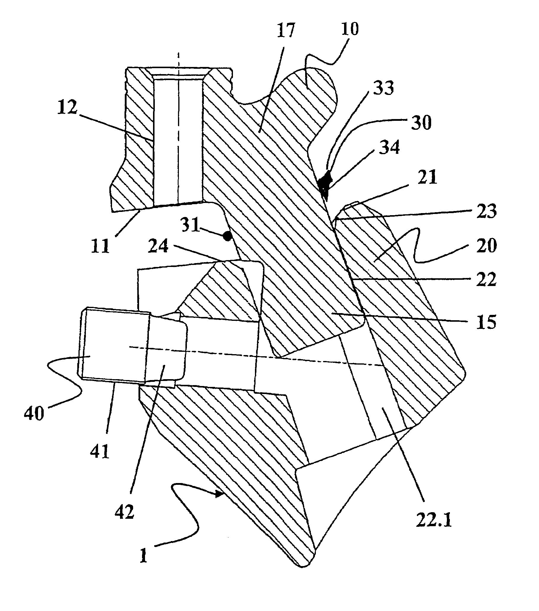
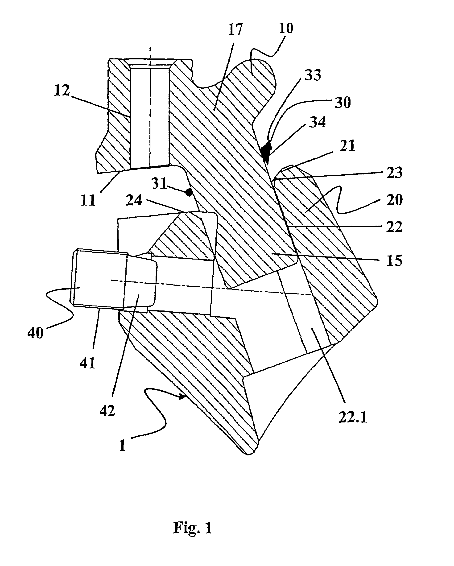
[0028]The cutting tool (1) in FIG. 1 comprises a base element (20), into which an exchangeable chisel holder (10) can be inserted. The cutting tool (1) has a sealing element (30) and a pressure screw (40), which is used for fixing the chisel holder (10) in place in the base element (20).

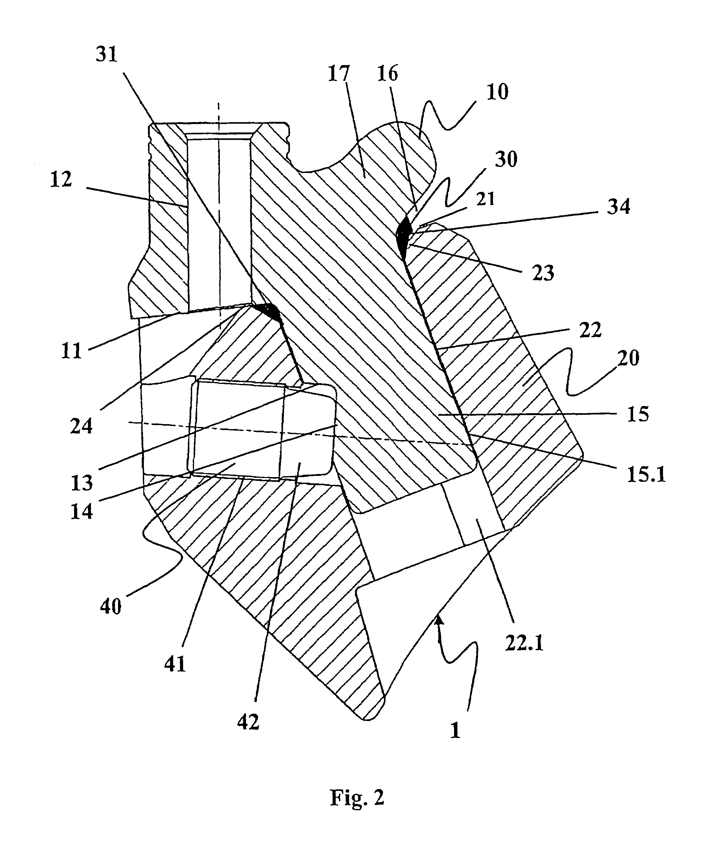
[0029]The chisel holder (10) includes a base body (17) and on its lower end has a plug-in shoulder (15), which can be inserted into a corresponding plug-in receptacle (22) at the base element (20). The insertion movement of the chisel holder (10) into the base element (20) is limited in its rear area by a stop (11) at the chisel holder (10) and by a stop (24) on the base element (20) located opposite it. On its front edge, the plug-in shoulder (15) has at least one guide face (15.1), which is guided during insertion of the chisel holder (10) by a corresponding V-guide (22.1) in the plug-in receptacle (22).

[0030]Also, the chisel holder (10) has a chisel receptacle (12), into which a turning chisel, wh...


PUM


Abstract

A cutting tool of a cutting machine having a base part and a bit holder. According to this invention, the bit holder has a plug-in attachment, retained in a socket of the base part that has a stop against which the bit holder rests. To prevent the penetration of water and stone dust and to allow the bit holder to be easily detached from the base part, a sealing element is located between the bit holder and the base part, surrounding at least sections of the socket.

Description

BACKGROUND OF THE INVENTION[0001]1. Field of the Invention[0002]This invention relates to a cutting tool of a cutting machine having a base element and a chisel holder, wherein the chisel holder has a plug-in shoulder which is retained in a plug-in receptacle of the base element, and wherein the plug-in receptacle is spatially connected with its surroundings via one or several openings.[0003]2. Discussion of Related Art[0004]A cutting tool is known from German Patent Reference DE 43 22 401 C2. The cutting tool contains a chisel holder and a base element which is fastened to a cylinder-shaped cutting body of a cutting machine. For fastening the chisel holder on the base element, the base element has a plug-in receptacle with a V-guide, into which a plug-in shoulder of the chisel holder can be pushed. The chisel holder is fixed in place using a pressure screw. Thus the exact positioning of the chisel holder has particular importance, also in case of repeated assembly / disassembly and e...

Claims


Application Information

Patent Timeline
Patent Type & Authority Patents(United States)
IPC IPC(8): E21C35/19A47C20/04E21C35/193
CPCA47C20/041E21C35/193Y10T82/2589E21C2035/191E21C35/191
Inventor TEWES, GUNTERHOLL, BERND
Owner WIRTGEN GMBH
Why Eureka
Try Eureka