Fluid separator with smart surface

a technology of smart surface and separator, which is applied in the direction of crystal growth process, machine/engine, electric/magnetic means, etc., can solve the problems of environmental concerns that may simultaneously complicate this approach, requiring a relatively high degree of purity of re-injected water, and generally not being able to achieve the environmentally responsible production of hydrocarbons, etc., to achieve enhanced separation speed and effect of speed and efficacy

Active Publication Date: 2008-12-09
HALLIBURTON ENERGY SERVICES INC
View PDF99 Cites 7 Cited by
  • Summary
  • Abstract
  • Description
  • Claims
  • Application Information

AI Technical Summary

Benefits of technology

[0007]According to one specific embodiment, a separating system separates constituents of a fluid mixture having different densities, such as water and oil. A conditioning vessel has a fluid inlet and a fluid outlet for passing the fluid mixture through the conditioning vessel. A smart surface within the conditioning fluid vessel has a plurality of surface-confined molecules sufficiently spaced to undergo conformational transitions in response to an applied voltage to preferentially expose hydrophilic or hydrophobic portions of the surface-confined molecules. A voltage source is used to selectively apply a voltage to the smart surface to attract or repel the water in proximity to the smart surface, thereby displacing the oil in proximity to the smart surface away from or toward the smart surface, respectively, thereby “conditioning” the fluid mixture to enhance separation. Conditioning the fluid usually also involves increasing the size of oil droplet or particles within the fluid mixture. A separator including a separator vessel is positioned downstream from the conditioning fluid vessel. The separator may include a conventional fluid separator, such as a gravitational, centrifugal, or hydrocyclonic separator. The separator receives and separates the conditioned fluid mixture and outputs the separated oil from an oil outlet and the separated water from a water outlet. Because the fluid mixture is conditioned prior to entering the separator, separation speed and efficacy are enhanced.

Problems solved by technology

Environmental concerns may simultaneously complicate this approach, however, requiring a relatively high degree of purity of the re-injected water.
Using existing separation techniques, the high degree of separation required by regulations and environmentally responsible production of hydrocarbons is generally not attainable.
In addition, if significant oil is injected into the disposal zone with the water, the water bearing formation may be adversely affected by the oil, causing blockage and / or reduced permeability of the injection interval.
Another problem with existing separation devices and methods is the amount of energy consumed in the process, and related costs.
Although the industry typically generates high revenues from the production of oil and gas, the associated costs are typically on the same order of magnitude.

Method used


Image

  • Fluid separator with smart surface
  • Fluid separator with smart surface
  • Fluid separator with smart surface

Examples


Embodiment Construction

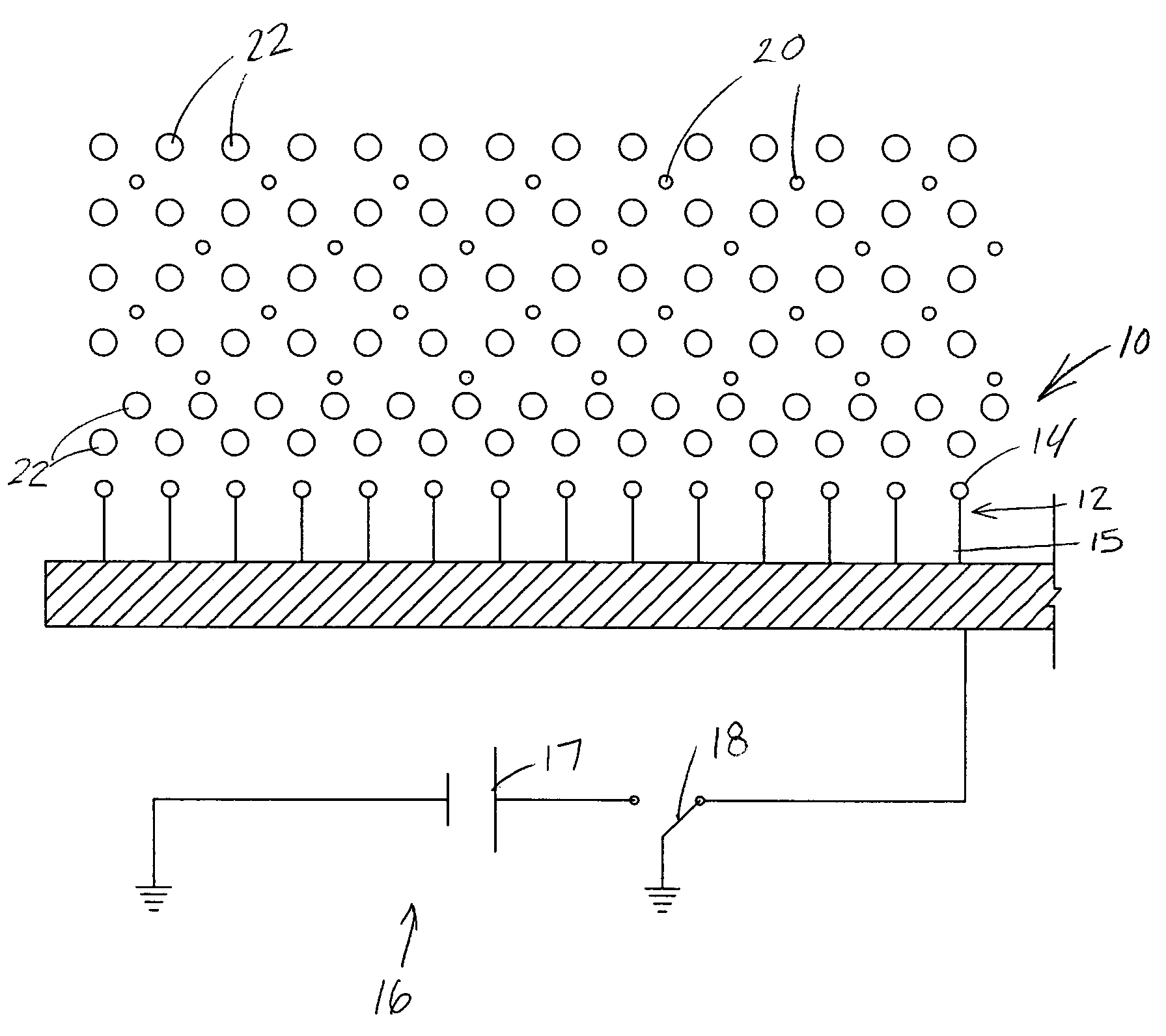
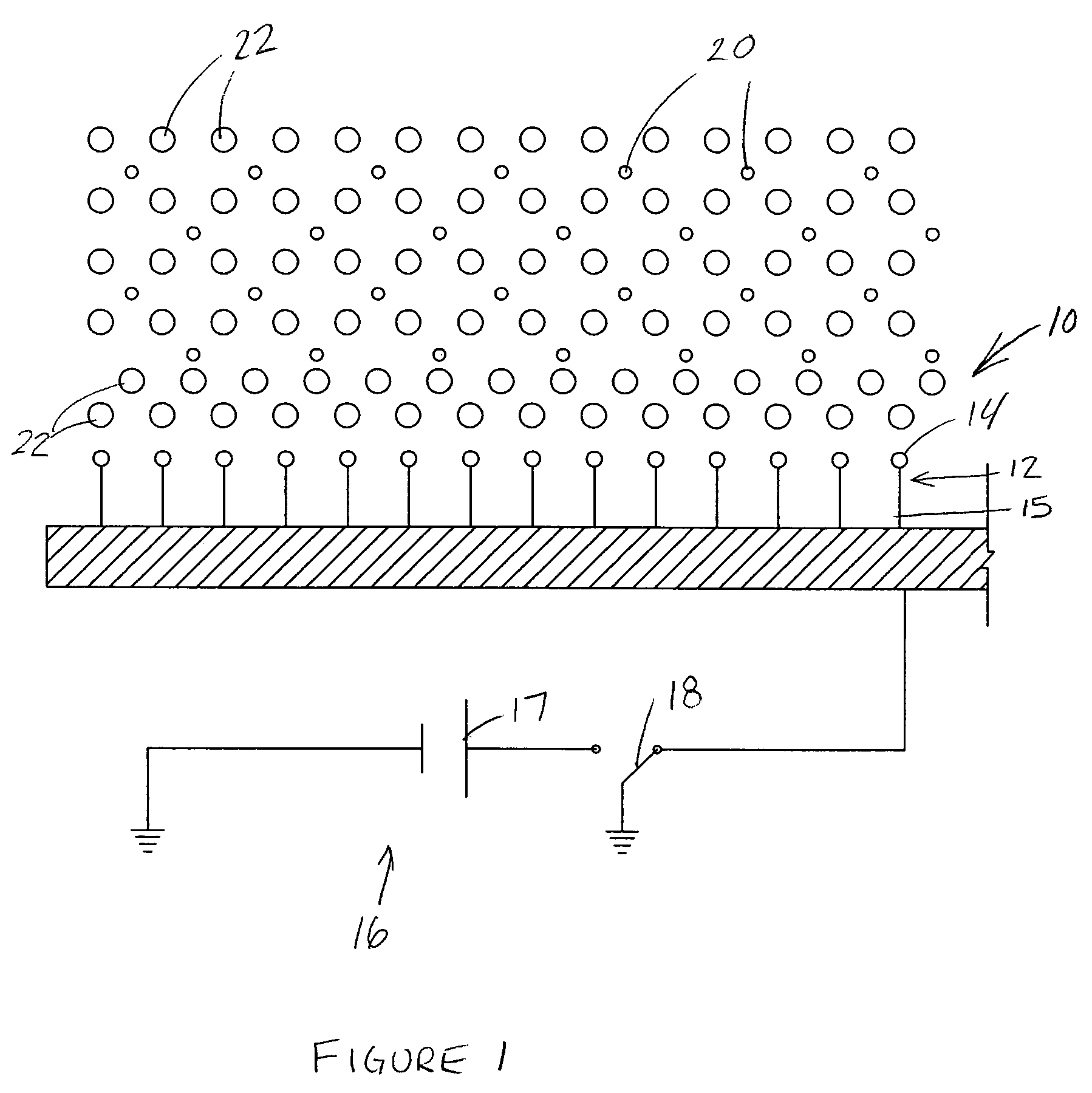
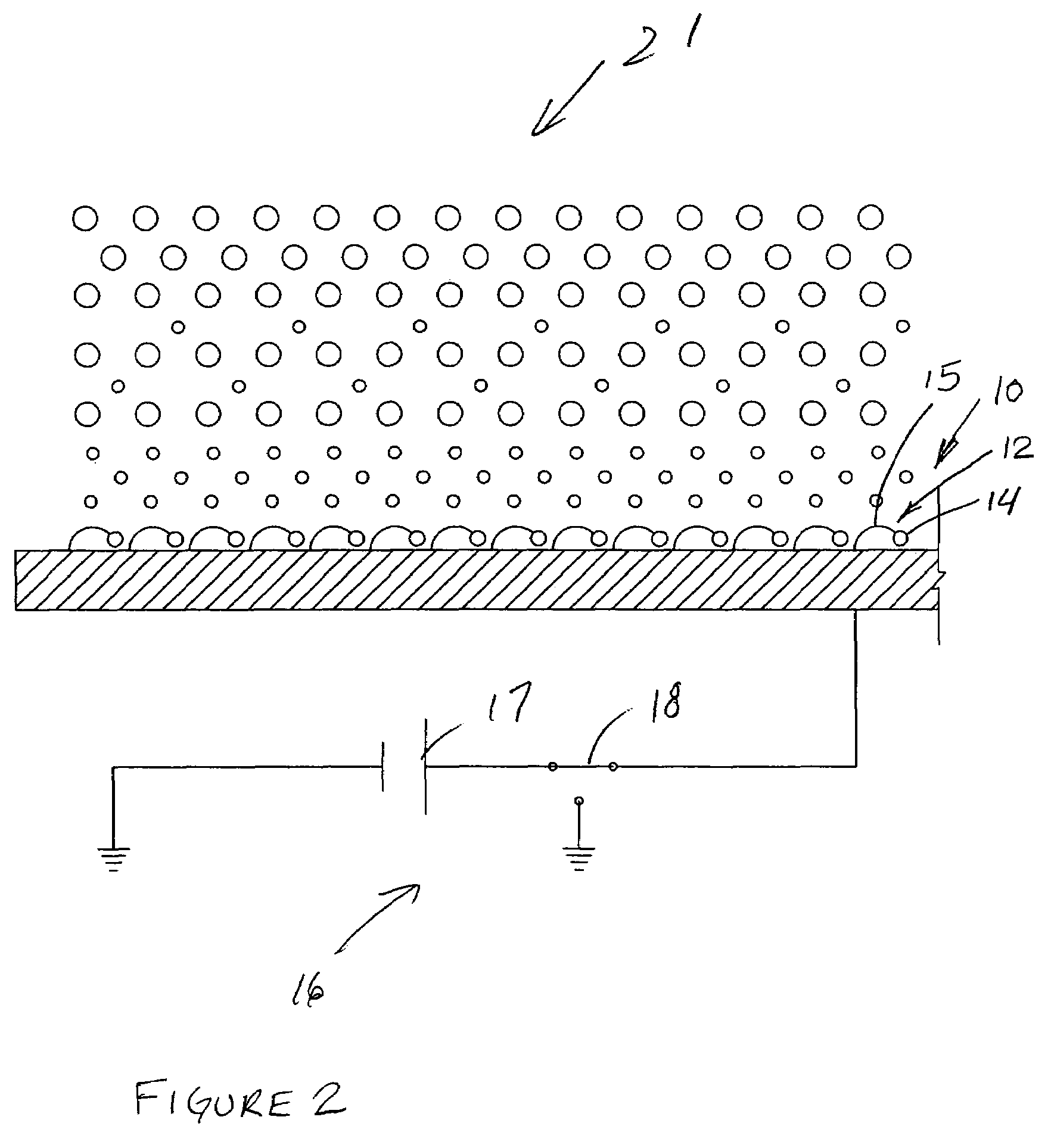
[0022]FIG. 1 conceptually illustrates a smart surface generally indicated at 10, having a plurality of surface-confined molecules 12 preferentially exposing hydrophilic portions 14 of the surface-confined molecules 12. A smart surface may be succinctly defined as a surface “having a plurality of surface-confined molecules sufficiently spaced to undergo conformational transitions in response to an applied voltage to preferentially expose hydrophilic or hydrophobic portions of the surface-confined molecules.” The chemistry and engineering involved, including the types of molecules selected and how they are produced and assembled to the smart surface 10, is generally known in this emerging art, and is therefore not discussed herein. A circuit conceptually indicated at 16 includes voltage source 17 and is wired to the smart surface 10. A voltage may be selectively applied to the surface 10 by closing the circuit 16 with gate 18. In FIG. 1, the circuit 16 is open to an “off” position, as...


PUM

PropertyMeasurementUnit
densityaaaaaaaaaa
hydrophilicaaaaaaaaaa
hydrophobicaaaaaaaaaa

Abstract

A separating system for separating a fluid mixture incorporates a smart surface having reversibly switchable properties. A voltage is selectively applied to the smart surface to attract or repel constituents of a fluid mixture, such as oil and water produced from a hydrocarbon well. The smart surface can be used in a conditioner to increase droplet size prior to entering a conventional separator, or the smart surface and other elements of the invention can be incorporated into an otherwise conventional separator to enhance separation. In a related aspect, a concentration sensor incorporating smart surfaces senses concentration of the fluid mixture's constituents.

Description

FIELD OF THE INVENTION[0001]The invention relates to separators for separating components of a fluid mixture. In particular, the invention relates to a separator using smart surfaces to enhance separation of oil and water produced from a downhole formation.BACKGROUND OF THE INVENTION[0002]A recent innovation in materials science is the development of “smart surfaces” that have reversible properties. In particular, scientists are developing an approach for “dynamically controlling interfacial properties that uses conformational transitions (switching) of surface-confined molecules.” (A Reversible Switching Surface—Science Magazine, 18 Oct. 2002). As explained further in MIT News (MIT's Smart surface Reverses Properties—Jan. 16, 2003), researchers describe “an example of their new approach in which they engineered a surface that can change from water-attracting to water-repelling with the application of a weak electric field. Switch the electrical potential of that field from positive...

Claims


Application Information

Patent Timeline
Patent Type & Authority Patents(United States)
IPC IPC(8): C02F1/461
CPCB03C5/02B03C9/00B03C2201/02
Inventor HAMID, SYEDMURALI, BEEGAMUDRE N.SMITH, JR., HARRY D.
Owner HALLIBURTON ENERGY SERVICES INC
Why Eureka
Try Eureka