Adaptive engine injection for emissions reduction

a technology of engine injection and emission reduction, which is applied in the direction of fuel injection apparatus, electric control, charge feed system, etc., can solve the problems of reducing the oxygen in the combustion regime, non-optimal combustion, and reducing the maximum combustion temperature, so as to improve the power output and reduce the injected fuel volume. , the effect of increasing the injection pressur

Active Publication Date: 2008-12-16
WISCONSIN ALUMNI RES FOUND
View PDF33 Cites 25 Cited by
  • Summary
  • Abstract
  • Description
  • Claims
  • Application Information

AI Technical Summary

Benefits of technology

[0013]Referring to C and D, a two-stage injection scheme is used over a range of greater engine loads. One or more starting greater load injections 102C / 102D are initially made between the start of the intake stroke and the end of the compression stroke, and these are followed by one or more ending greater load injections 104C / 104D which occur prior to the end of the expansion stroke. The starting greater load injections 102C / 102D, like the low load injections 100A / 100B, are intended to create a lean and highly premixed fuel-air charge within the combustion chamber 14. The ending greater load injections 104C / 104D are intended to utilize the remaining air within the chamber 14 and generate further work output, while at the same time maintaining combustion and heat release at a controlled rate, avoiding potentially damaging rapid chamber pressure increases, and avoiding the temperature extremes that give rise to NOx production, as well as avoiding the soot that accompanies uneven fuel / air distribution within the chamber 14.
[0015]The ending greater load injections 104C / 104D preferably occur after approximately 90 degrees before top dead center during the compression stroke (i.e., midway through compression), and before approximately 90 degrees after top dead center during the expansion stroke (i.e., midway through expansion). Preferably, they begin at or closely adjacent the end of the compression stroke to enhance power output. Each ending greater load injection 104C / 104D has higher injection pressure than any of the starting greater load injections 102C / 102D (preferably greater than approximately 50 MPa and most preferably above approximately 100 MPa), and lower injected fuel volume than the total injected fuel volume of all starting greater load injections 102C / 102D. Additionally, the total injected fuel volume of all ending greater load injections 104C / 104D is preferably less than the total injected fuel volume of all starting greater load injections 102C / 102D.
[0016]As illustrated at D in FIG. 1, the ending greater load injections 104D may include one or more peak injections 106D with greater pressure (and injected fuel volume)—usually situated at or shortly after top dead center at the end of the compression stroke, for greater power output—with any prior or later greater load injections 104D decreasing in injection pressure and fuel volume as these injections are spaced in time from the peak injection(s) 106D. This variation in injection pressure helps attain adequate fuel penetration within the combustion chamber 14, i.e., the injected fuel will traverse the chamber 14 to a sufficient degree that it will more readily reach the available air in the chamber 14 as the gas density within the chamber 14 varies. At the same time, the injection pressure is modified such that the injected fuel does not impinge (or minimally impinges) on the walls of the chamber 14, an effect which adversely affects fuel economy and emissions.

Problems solved by technology

This reduces the oxygen in the combustion regime and reduces the maximum combustion temperature, thereby deterring NOx formation.
Soot includes a variety of matter such as elemental carbon, heavy hydrocarbons, hydrated sulfuric acid, and other large molecules, and are generally associated with non-optimal combustion.
Unfortunately, measures which reduce NOx tend to increase soot emissions, and measures which reduce soot tend to increase NOx emissions, resulting in what is often termed the “soot-NOx tradeoff”.
At the time of this writing, the diesel engine industry is facing stringent emissions legislation in the United States, and is struggling to find methods to meet government-imposed NOx and soot restrictions.
This requires considerable expense and complexity, particularly since additional fuel must often be mixed and ignited in the exhaust stream in order to burn off the accumulated soot deposits.

Method used


Image

  • Adaptive engine injection for emissions reduction
  • Adaptive engine injection for emissions reduction

Examples


Embodiment Construction

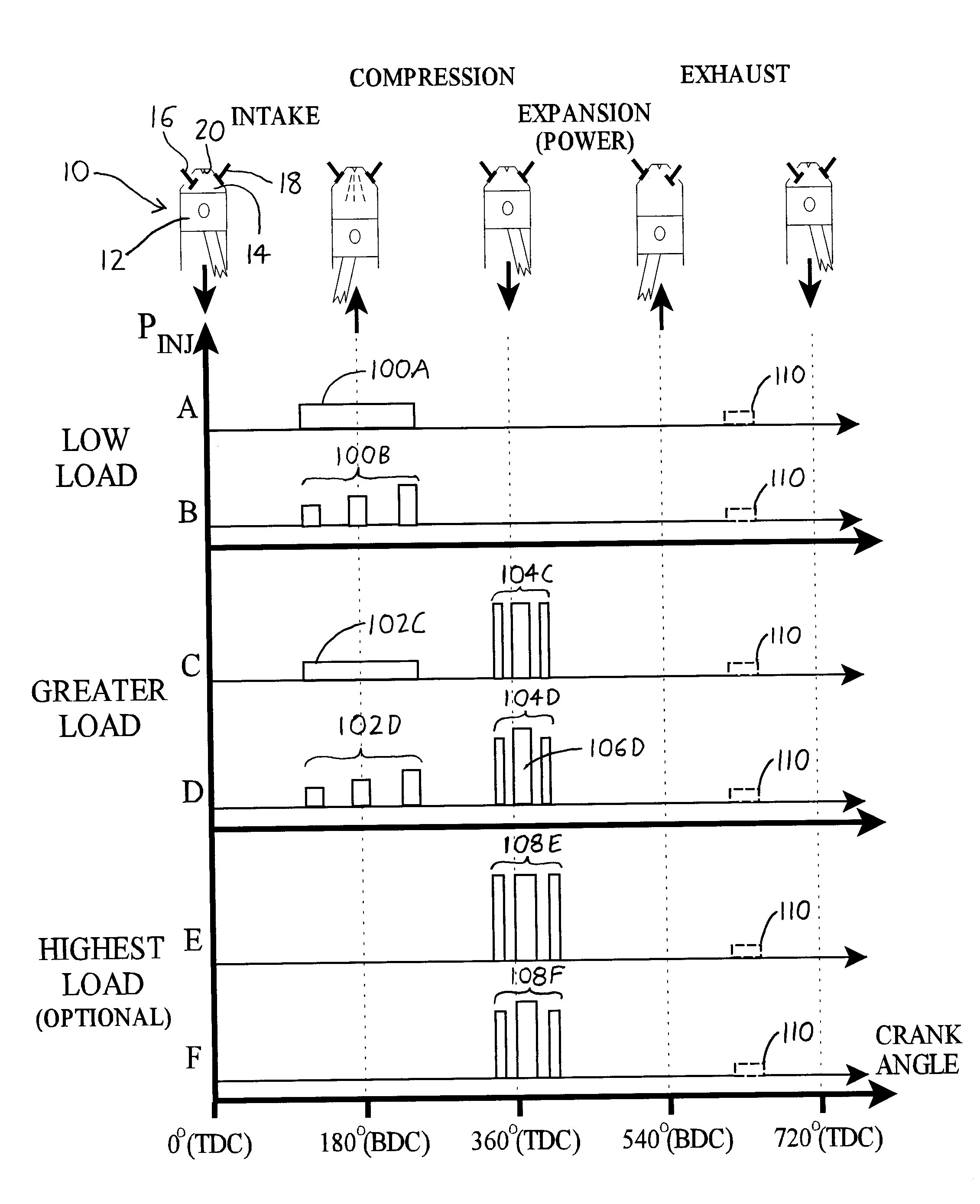
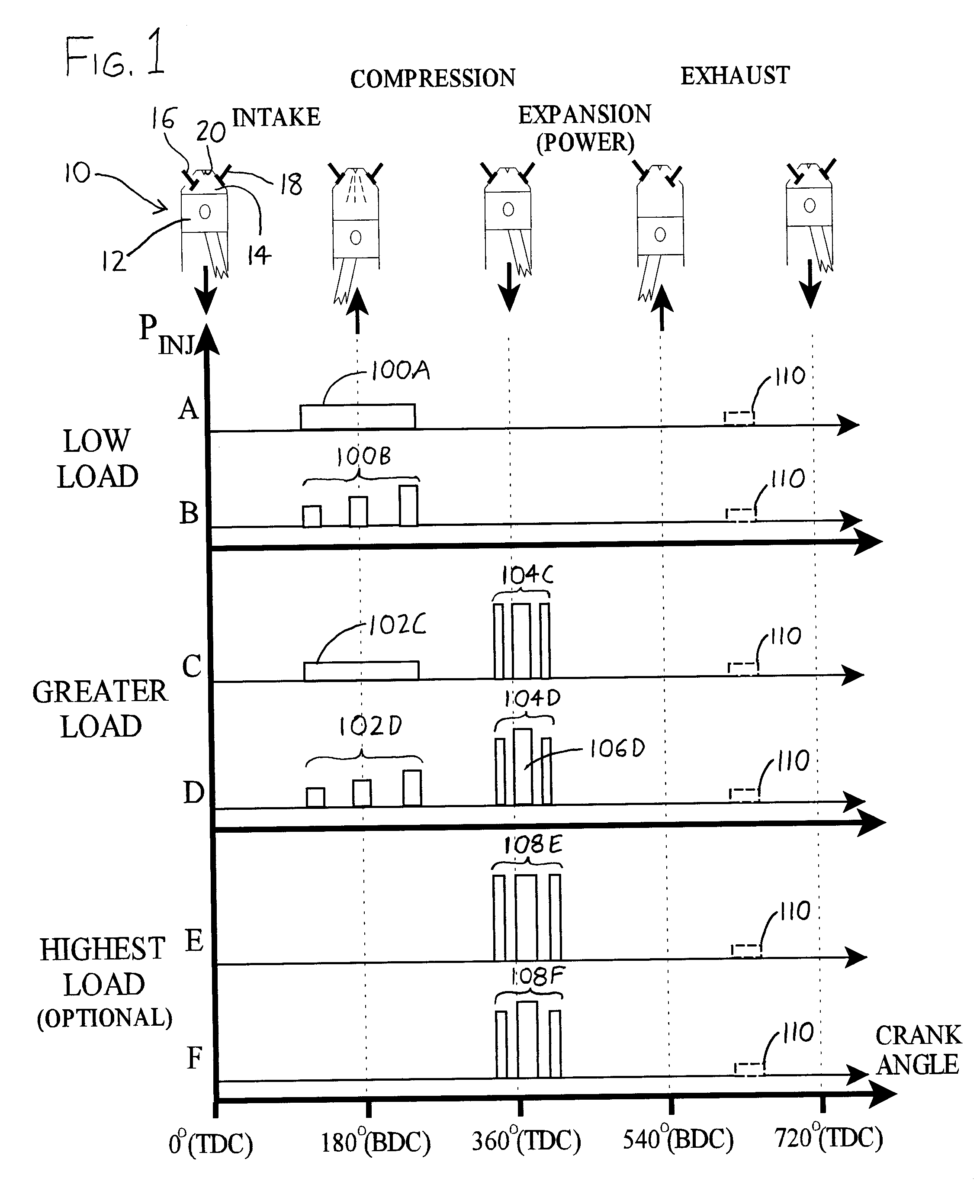
[0022]Expanding on the foregoing discussion, it should be understood that the injection curves of FIG. 1 are merely exemplary, and the timing of injections, the duration of these injections, the profile shape of each injected charge, and the relative heights (i.e., the relative rates / pressures) for the various injection methods may in practice vary widely. As an example, in place of the depicted single constant pressure low load injection 100A and starting greater load injection 102C, or the multiple increasing-pressure low load injections 100B and starting greater load injections 102D, a single increasing-pressure low load injection might be made, i.e., the profile of the injections 100A and 102C could be modified so that pressure increases over the course of the injection. In similar respects, the profile of each of the injections within 100B and / or 102D could be modified to increase over the course of the injection, and / or the profiles of the injections within 104C and / or 104D an...


PUM


Abstract

NOx and soot emissions from internal combustion engines, and in particular compression ignition (diesel) engines, are reduced by varying fuel injection timing, fuel injection pressure, and injected fuel volume between low and greater engine loads. At low loads, fuel is injected during one or more low-pressure injections occurring at low injection pressures between the start of the intake stroke and approximately 40 degrees before top dead center during the compression stroke. At higher loads, similar injections are used early in each combustion cycle, in addition to later injections which preferably occur between about 90 degrees before top dead center during the compression stroke, and about 90 degrees after top dead center during the expansion stroke (and which most preferably begin at or closely adjacent the end of the compression stroke). These later injections have higher injection pressure, and also lower injected fuel volume, than the earlier injections.

Description

STATEMENT REGARDING FEDERALLY SPONSORED RESEARCH[0001]This invention was made with United States government support awarded by the following agencies:[0002]U.S. Department of Energy (DOE) Grant No.: DE-FC26-06NT42628 The United States has certain rights in this invention.FIELD OF THE INVENTION[0003]This document concerns an invention relating generally to methods and devices for reducing emissions from internal combustion engines, and more specifically to methods and apparata for reducing soot and NOx emissions from internal combustion engines (and in particular diesel engines).BACKGROUND OF THE INVENTION[0004]Common pollutants arising from the use of internal combustion engines are nitrogen oxides (commonly denoted NOx) and particulate matter (also known simply as “soot”). NOx is generally associated with high-temperature engine conditions, and may be reduced by use of measures such as exhaust gas recirculation (EGR), wherein the engine intake air is diluted with relatively inert e...

Claims


Application Information

Patent Timeline
Patent Type & Authority Patents(United States)
IPC IPC(8): F02B3/00F02B3/04
CPCF02D41/3035F02D41/3836F02D41/402F02M45/02Y02T10/44Y02T10/40
Inventor REITZ, ROLF D.SUN, YONG
Owner WISCONSIN ALUMNI RES FOUND
Why Eureka
Try Eureka