Cogeneration system

a cogeneration system and cogeneration technology, applied in mechanical energy handling, steam use, heat storage plants, etc., can solve the problems of complex arrangement, complex control operation, and degradation of operability, and achieve simple control operation, simple arrangement, and enhanced operability

Inactive Publication Date: 2008-12-16
LG ELECTRONICS INC
View PDF9 Cites 33 Cited by
  • Summary
  • Abstract
  • Description
  • Claims
  • Application Information

AI Technical Summary

Benefits of technology

[0011]The present invention has been made in view of the above-mentioned problems, and it is an object of the invention to provide a cogeneration system wherein an engine, a generator, a waste heat recoverer, and a radiator are combined into a single unit, so that the cogeneration system has a compact and simple arrangement, and achieves simple control operations, and an enhancement in operability.

Problems solved by technology

Accordingly, the conventional cogeneration system has problems of a complex arrangement, sophisticated control operations, a degradation in operability, and a reduction in the amount of waste heat transferred to the heat consumer 30.

Method used


Image

  • Cogeneration system
  • Cogeneration system
  • Cogeneration system

Examples


second embodiment

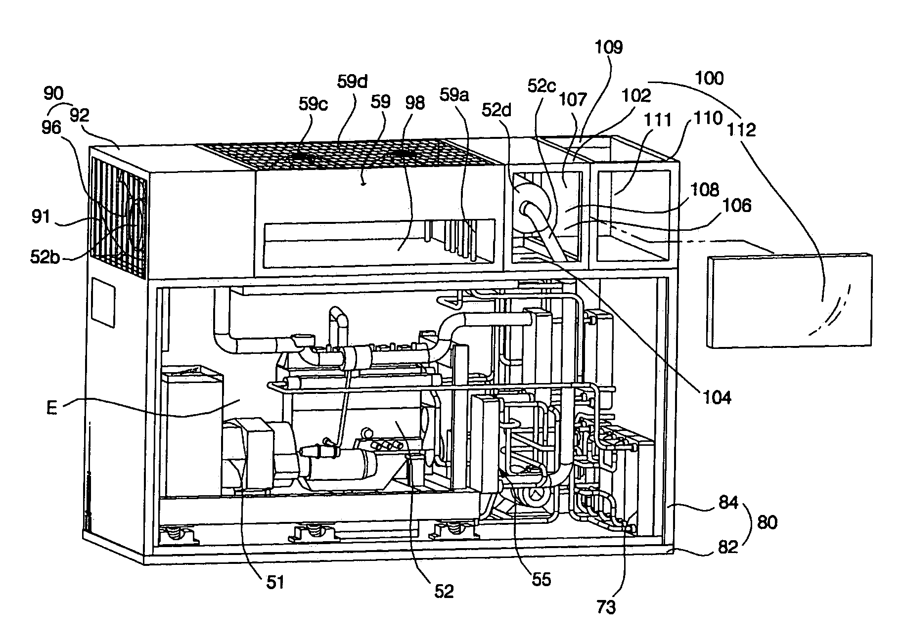
[0098]FIG. 6 is an exploded perspective view of a cogeneration system according to the present invention.

[0099]As shown in FIG. 6, in the cogeneration system according to this embodiment, the waste heat supplier 73 is not arranged in the cogeneration unit 50, but is arranged in the outdoor unit A or in a separate unit (not shown). The cogeneration system of this embodiment has the same configuration and functions as those of the first embodiment, except for the waste heat supplier 73. Accordingly, the constituent elements of the second embodiment respectively corresponding to those of the first embodiment are designated by the same reference numerals, and no detailed description thereof will be given.

first embodiment

[0100]The waste heat supplier 73 may constitute the second outdoor heat exchanger adapted to evaporate the refrigerant circulated through the heat pump type air conditioner 60, as in the Alternately, the waste heat supplier 73 may constitute a pre-heater arranged in the outdoor unit A to pre-heat outdoor air sucked into the first outdoor heat exchanger or a compressor discharge line heater arranged in the outdoor unit A to heat the refrigerant compressed in the compressors of the outdoor unit A.

[0101]The cogeneration system according to any one of the above-described embodiments of the present invention has various effects.

[0102]That is, first, the cogeneration system according to the present invention has advantages in that the cogeneration system has a compact and simple arrangement, and achieves simple control operations, and an enhancement in operability because the generator, which generates electricity, the drive source, which operates to drive the generator, and generates wa...


PUM


Abstract

A cogeneration system is disclosed, wherein a generator which generates electricity, a drive source which operates to drive the generator, and generates waste heat during the operation of the drive source, a waste heat recoverer which recovers the waste heat of the drive source, and a radiator which radiates the waste heat recovered by the waste heat recoverer are arranged in a single chassis. The cogeneration system has a compact and simple arrangement, and achieves simple control operations, and an enhancement in operability.

Description

BACKGROUND OF THE INVENTION[0001]1. Field of the Invention[0002]The present invention relates to a cogeneration system, and, more particularly, to a cogeneration system wherein a generator, a drive source adapted to drive the generator, and a waste heat recoverer adapted to recover waste heat from the drive source are arranged in a single chassis.[0003]2. Description of the Related Art[0004]FIG. 1 is a schematic view illustrating a conventional cogeneration system.[0005]As shown in FIG. 1, the conventional cogeneration system includes a generator 2 to generate electricity, a drive source 10, which operates to drive the generator 2, and generates waste heat during operation thereof, such as an engine (hereinafter, the drive source 10 will be referred to as an “engine”), a waste heat recoverer 20 to recover waste heat generated from the engine 10, and a heat consumer 30 to use the waste heat recovered by the waste heat recoverer 20, such as a thermal storage tank.[0006]The electricity...

Claims


Application Information

Patent Timeline
Patent Type & Authority Patents(United States)
IPC IPC(8): H02P9/04F24F1/00
CPCF25B27/02F24F1/06F24F1/44F24F1/56F25B13/00Y02E20/14Y02T10/16F02B63/044Y02P80/15Y02A30/274Y02T10/12Y02E60/14F28D20/00
Inventor KANG, SEUNG TAKCHOI, CHANG MINCHOI, WON JAELIM, HYUNG SOOHWANG, YOON JEI
Owner LG ELECTRONICS INC
Why Eureka
Try Eureka