Current sensor

a current sensor and sensor technology, applied in the field of current sensors, can solve problems such as linearity deterioration, measurement error may be caused, measurement accuracy may be deteriorated,

Active Publication Date: 2015-01-22
YOKOGAWA ELECTRIC CORP
View PDF3 Cites 11 Cited by
  • Summary
  • Abstract
  • Description
  • Claims
  • Application Information

AI Technical Summary

Problems solved by technology

In detecting the magnitude of the current flowing in a cable in a contactless manner, a measurement error may be caused when the relative position between the center of the cable and the current sensor is shifted.
It is noted that the displacement-caused error refers to a measurement error that occurs when there is a shift in the relative position between the current sensor and the cable in which the measured current flows.
When the magnetism collection core is used, however, the measurement accuracy may be deteriorated because of a dis

Method used


Image

  • Current sensor
  • Current sensor
  • Current sensor

Examples


Embodiment Construction

[0033]In the following detailed description, for purpose of explanation, numerous specific details are set forth in order to provide a thorough understanding of the disclosed embodiments. It will be apparent, however, that one or more embodiments may be practiced without these specific details. In other instances, well-known structures and devices are schematically shown in order to simplify the drawing.

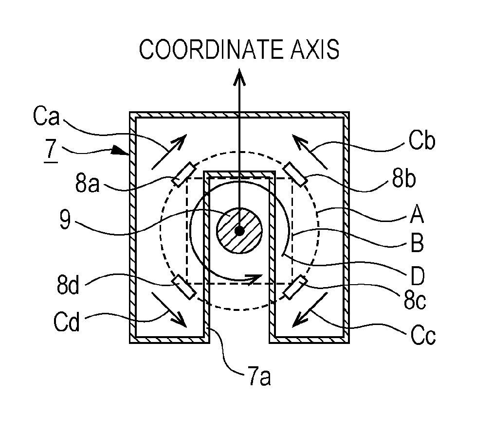
[0034]In the conventional arrangement illustrated in FIG. 18, the sensitivities of the hole elements 4 are relatively low, which results in a low sensitivity as a current sensor. In order to increase the sensitivity as a current sensor as much as possible, it can be considered to use more elements. In this case, however, the size of the current sensor will increase, which results in the increase in the number of parts and the cost.

[0035]One of the purposes of the present disclosure is to achieve a current sensor using magnetic sensor elements that consumes less power, has a high sens...


PUM


Abstract

A current sensor includes: four magnetic sensor elements arranged within a plane orthogonal to a measured current, having a symmetrical magnetic characteristics curve, and adapted to convert a magnitude of a magnetic field into an electrical signal and output the electrical signal; a bridge circuit including the four magnetic sensor elements; and a bias magnetic field application member adapted to applying a bias magnetic field to the magnetic sensor elements.

Description

CROSS-REFERENCE TO RELATED APPLICATION[0001]This application claims priority from Japanese Patent Application Nos. 2013-147732 filed with the Japan Patent Office on Jul. 16, 2013 and 2014-008274 filed with the Japan Patent Office on Jan. 21, 2014, the entire contents of which are hereby incorporated by reference.BACKGROUND[0002]1. Technical Field[0003]The present disclosure relates to a current sensor using magnetic sensor elements.[0004]2. Related Art[0005]As a type of current sensor, current sensors using magnetic sensor elements have been known. The magnetic sensor element converts a magnitude of a magnetic field into an electric signal based on the change in the electric resistance, the electromotive force, or the like and outputs the electric signal.[0006]In detecting the magnitude of the current flowing in a cable in a contactless manner, a measurement error may be caused when the relative position between the center of the cable and the current sensor is shifted.[0007]Therefo...

Claims


Application Information

Patent Timeline
IPC IPC(8): G01R19/00
CPCG01R19/0092G01R15/205G01R33/091G01R15/207
Inventor MITO, SHINYATAKENAKA, KAZUMAKATO, SATOSHI
Owner YOKOGAWA ELECTRIC CORP
Why Eureka
Try Eureka