Lens barrel and imaging apparatus

a technology of lens barrel and imaging apparatus, which is applied in the direction of mountings, optics, instruments, etc., can solve the problems of large difference inconvenient adjustment of the optical axis of the group of lenses, and inability to move smoothly between the rotating cam barrel and the stationary barrel, etc., to achieve convenient adjustment, small sliding motion, and sufficient space

Inactive Publication Date: 2008-12-16
SONY CORP
View PDF2 Cites 18 Cited by
  • Summary
  • Abstract
  • Description
  • Claims
  • Application Information

AI Technical Summary

Benefits of technology

[0023]In the lens barrel, according to the embodiment of the invention, the pressing roller includes disk-shaped slidable projections jutting out in opposite directions from the side surfaces of the roller portion, each of the slidable projections being slidable on an end of the opening of the roller support hole in the first moving frame. The amount of projection of the slidable projection from the roller portion is smaller than the amount of projection of the shaft, with the diameter of the slidable projection being smaller than the diameter of the roller portion and greater than the diameter of the shaft. Therefore, the areas that come into contact with the ends of the opening of the roller support hole are small when the pressing roller rotates and the loss due to the sliding motion is small accordingly. It is thus possible to ensure a smooth rotation of the pressing roller.
[0024]In the lens barrel, according to the embodiment of the invention, the biasing spring includes a first flat spring and a second flat spring, and the first and second flat springs are overlaid in the thickness direction. Therefore, the spring constant of the biasing spring is larger than that of a flat spring having the total thickness of the first and second flat springs biasing spring is unlikely to be plastically deformed, and hence the functionality of the biasing spring can be improved.
[0025]In the lens barrel, according to the embodiment of the invention, the cam ring is shaped into a substantially cylindrical form, with the first moving frame including a cylindrical portion and a flat portion connected to the cylindrical portion in the circumferential direction. The portion of the first moving frame that includes at least the flat portion is disposed inside the cam ring, and the flat portion is a spring attachment portion to which the biasing spring is attached. It is therefore possible to provide a sufficient space for disposing the biasing springs without increasing the size of the lens barrel.
[0026]In the lens barrel, according to the embodiment of the invention, the biasing spring includes a first flat spring and a second flat spring, with the outer shape of being smaller than the outer shape of the first flat spring. The first flat spring is disposed in such a way that the first flat spring is in contact with the spring attachment portion, and the second flat spring is overlaid on the first flat spring in the thickness direction. Therefore, the biasing spring does not take up a large area and fits in a space created between the flat portion and the inner surface of the cam ring, resulting in effective use of the layout space.
[0027]In the lens barrel, according to the embodiment of the invention, a plurality of receive rollers is provided at locations spaced apart in the optical axis direction. Therefore, the first and second movable units are unlikely to be inclined to the optical axis in the optical axis direction. It is thus possible to improve the stability of the motion of the first and second movable units and hence the image quality.
[0028]In the lens barrel according to the embodiment of the invention, a plurality of receive rollers is provided at locations spaced apart in a direction perpendicular to the optical axis. Therefore, the first and second movable units are unlikely to be inclined to the optical axis in a direction perpendicular to the optical axis. It is thus possible to improve the stability of the motion of the first and second movable units and hence the image quality.

Problems solved by technology

In the imaging apparatus described in JP-A-2000-266981, however, since the cam barrel is pressed against the stationary barrel when rotated to move the movable unit in the optical axis direction, the friction between the rotating cam barrel and the stationary barrel is large, and hence the cam barrel will not move smoothly in a disadvantageous manner.
On the other hand, when the biasing force that presses the cam barrel against the stationary barrel is reduced to ensure the smoothness of the motion, the group of lenses is likely to be inclined to the optical axis of the group of lenses in an inconvenient manner.

Method used


Image

  • Lens barrel and imaging apparatus
  • Lens barrel and imaging apparatus
  • Lens barrel and imaging apparatus

Examples


Embodiment Construction

[0040]The best mode for carrying out a lens barrel and an imaging apparatus according to embodiments of the invention will be described below with reference to the accompanying drawings.

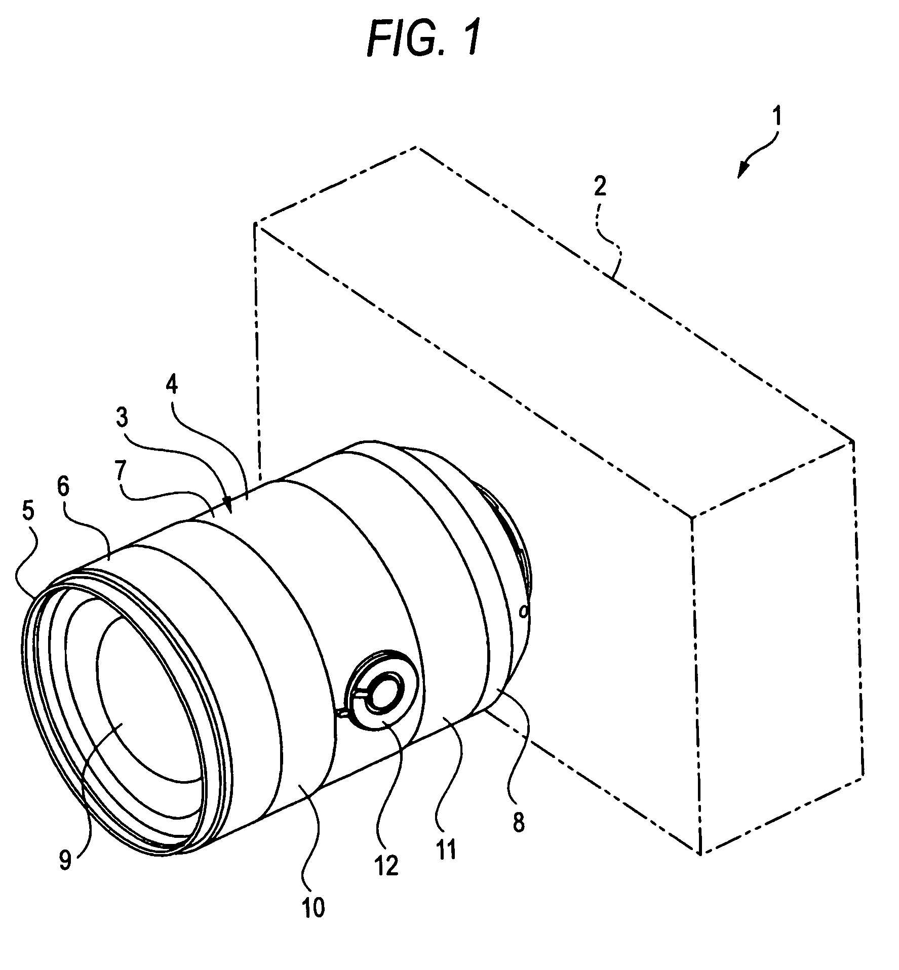
[0041]The best mode described below is an imaging apparatus according to an embodiment of the invention applied to a still camera and a lens barrel according to an embodiment of the invention applied to a lens barrel provided in the still camera. The scope of the invention, however, is not limited to a still camera or a lens barrel provided in the still camera. For example, the best mode is widely applicable to various imaging apparatuses incorporated in a video camera and other apparatuses or a lens barrel provided in such various imaging apparatuses.

[0042]In the following description, the front-rear, up-down, and right-left directions are defined relative to an user who uses a still camera to acquire an image. That is, the subject side is the front side, and the camera user side is the rear side.

[0...


PUM


Abstract

A lens barrel in which a plurality of movable units, each including a group of lenses, are moved in the optical axis direction when a cam ring is rotated relative to a stationary ring around the optical axis, is disclosed. The lens barrel includes a first movable unit including a first group of lenses and a first moving frame having a roller support hole formed therein; a second movable unit including a second group of lenses and a second moving frame disposed inside the first moving frame; a pressing roller supported in the roller support hole in the first moving frame; a biasing spring attached to the outer surface of the first moving frame; and a receive roller supported by the first or second moving frame.

Description

CROSS REFERENCES TO RELATED APPLICATIONS[0001]The present invention contains subject matter related to Japanese Patent Application JP 2007-193510 filed in the Japanese Patent Office on Jul. 25, 2007, the entire contents of which are incorporated herein by reference.BACKGROUND OF THE INVENTION[0002]1. Field of the Invention[0003]The present invention relates to the technical field of a lens barrel and an imaging apparatus, particularly the technological field in which a biasing spring presses a pressing roller supported by a first moving frame against a second moving frame to prevent a group of lenses from being inclined to the optical axis so as to improve, for example, optical performance.[0004]2. Description of the Related Art[0005]Some imaging apparatuses, such as a still camera and a video camera, include a lens barrel having a plurality of groups of lenses movable in the optical axis direction for focusing and zooming.[0006]Examples of such lens barrels include a lens barrel as...

Claims


Application Information

Patent Timeline
Patent Type & Authority Patents(United States)
IPC IPC(8): G02B7/02
CPCG02B7/102
Inventor KOYAMA, TAKASHI
Owner SONY CORP
Why Eureka
Try Eureka