Ballast with arc protection circuit

a protection circuit and ballast technology, applied in the direction of electric variable regulation, process and machine control, instruments, etc., can solve the problems of high intensity, sustained arc (, opposed to momentary arc) may occur

Inactive Publication Date: 2008-12-23
OSRAM SYLVANIA INC
View PDF6 Cites 8 Cited by
  • Summary
  • Abstract
  • Description
  • Claims
  • Application Information

AI Technical Summary

Problems solved by technology

As another example, a sustained arc (as opposed to a momentary arc) may occur due to poor or faulty connections in the output wiring or the lamp sockets, or if a lamp is improperly installed in such a way that a small gap exists between the lamp pins and the contacts within the fixture sockets.
If a connection to a lamp is compromised due to a defective lamp socket or defective wiring, a high intensity, high temperature arc may be produced across the air gap caused by those faulty connections.
Arcing is generally acknowledged to cause degradation of the contacts in the fixture sockets and undue stress on components within the ballast.
Sustained arcing is especially undesirable because of its tendency to produce potentially destructive heating.
This requirement poses a considerable inconvenience in many applications, such as in large office areas or factories, in which a large number of ballasts are often connected in the same branch circuit.
For instance, the normal starting process of the inverter and lamps is generally accompanied by the same types of electrical disturbances that occur during an arc condition.
Additionally, although most lamps are capable, under ideal conditions, of igniting and operating normally within a short period of time (e.g., 20 milliseconds), some lamps, due to age or low temperature, require a much longer time to ignite and stabilize.
Also, because lamps are somewhat unpredictable, it is possible that an otherwise “good” lamp may sometimes fail to properly start on the first attempt.
This regular brief flashing, which occurs on a sustained basis until either the arc condition is corrected or power is removed from the ballast, is considered to be visually annoying to occupants who are in the vicinity of the affected lighting fixture.
Additionally, the periodic restart attempts are stressful to the components within the ballast.
Yet another shortcoming of many existing approaches to arc protection is that those circuits often require a considerable amount of operating power.
Typically, the operating power requirements increase with circuit complexity, especially when analog circuitry is extensively employed.
Consequently, those circuits significantly detract from the overall energy efficiency of the ballast.
However, providing reliable arc protection within these types of ballasts presents a significant engineering challenge.
In particular, many prior art approaches are susceptible to problems relating to arc detection resolution, and are therefore ill-suited for ballasts that power multiple (e.g., three or four) lamps.
Because of this problem, one existing approach has been to provide a separate inverter and output circuit for each of the lamps powered by the ballast; such an approach has the obvious disadvantage of being quite expensive, especially for ballasts that power three or four lamps (in which case three or four separate inverters and output circuits are required).
The output wiring that is present between the output of the ballast and the lamp fixture introduces a certain amount of stray capacitance.
That stray capacitance may impact the ability of an arc protection circuit to reliably detect the presence of an arc condition.

Method used


Image

  • Ballast with arc protection circuit
  • Ballast with arc protection circuit
  • Ballast with arc protection circuit

Examples


Embodiment Construction

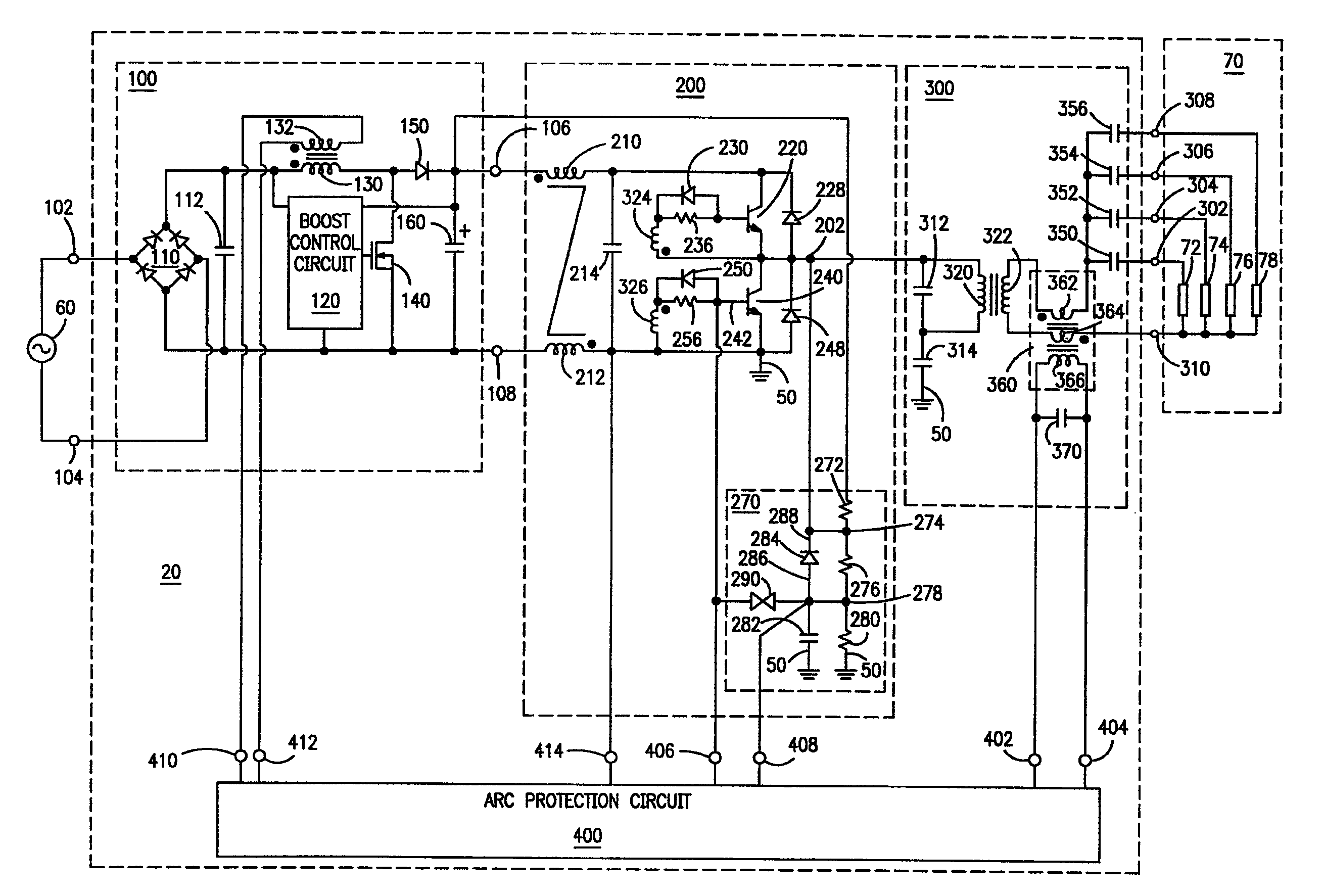
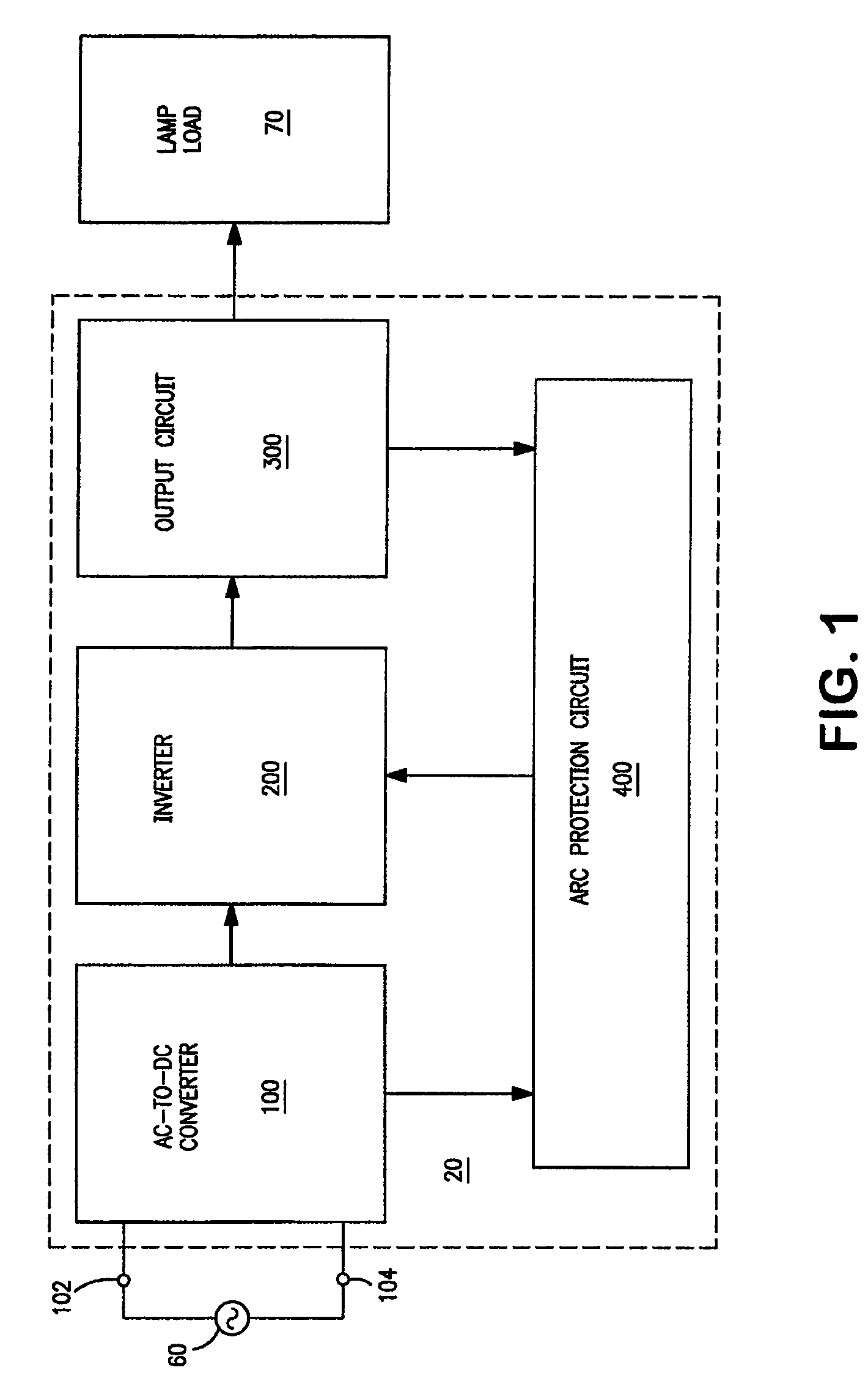
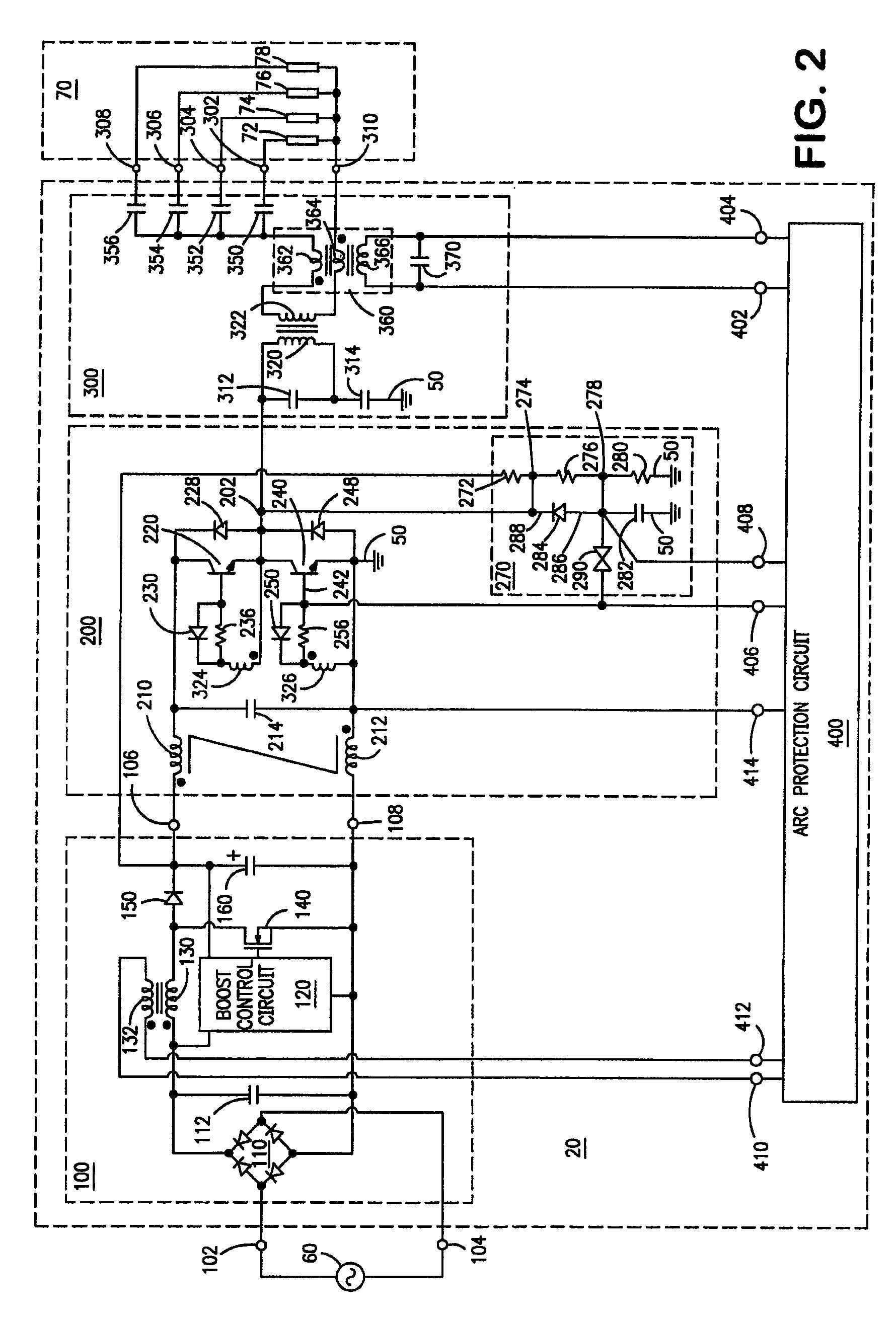
[0020]Referring to FIG. 1, a ballast 20 for powering a lamp load 70 (that includes one or more gas discharge lamps) comprises an AC-to-DC converter 100, an inverter 200, an output circuit 300, and an arc protection circuit 400. AC-to-DC converter 100 has inputs 102,104 for receiving an AC supply voltage 60 (e.g., 277 volts rms at 60 hertz). During operation, AC-to-DC converter 100 provides a DC rail voltage to inverter 200. Inverter 200 is characterized by having a normal operating frequency (e.g., 40 kilohertz); that is, the operating frequency of inverter 200 is normal when at least each of the lamps within lamp load 70 is operating in substantially normal manner, and when at least no arc condition is present at any of the sockets within the lighting fixture to which the lamps (within lamp load 70) are connected. Output circuit 300 is coupled to inverter 200, and is adapted for coupling to lamp load 70. Arc protection circuit 400 is coupled to inverter 200 and output circuit 300; ...


PUM


Abstract

A ballast (20) for powering one or more gas discharge lamps (70,72,74,76) comprises an inverter (200), an output circuit (300), and an arc protection circuit (400). Arc protection circuit (400) monitors an electrical signal within the output circuit (300). When an arcing condition occurs at the ballast output connections (302,304,306,308,310), the electrical signal includes a high frequency component having a fundamental frequency that is much greater than the normal operating frequency of the inverter (200). In response to the high frequency component exceeding a predetermined threshold, arc protection circuit (400) disables the inverter (200) for a predetermined shutdown period. Arc protection circuit (400) also provides a restart function for periodically attempting to ignite and operate the lamps. Arc protection circuit (400) is preferably realized using a microcontroller integrated circuit (440) with associated discrete circuitry, and is especially well-suited for use in ballasts for powering multiple lamps via a current-fed self-oscillating inverter and an isolated parallel resonant output circuit.

Description

CROSS REFERENCE TO RELATED APPLICATION[0001]This is a division of prior application Ser. No. 11 / 532,277, filed on Sep. 15, 2006, which is hereby incorporated herein by reference in its entirety.FIELD OF THE INVENTION[0002]The present invention relates to the general subject of circuits for powering discharge lamps. More particularly, the present invention relates to a ballast that includes a circuit for protecting against output arcing.RELATED APPLICATIONS[0003]The subject matter of the present application is related to that of U.S. Pat. No. 6,720,739 B2 (titled “Ballast with Protection Circuit for Quickly Responding to Electrical Disturbances,” issued on Apr. 13, 2004, and assigned to the same assignee as the present application), U.S. Pat. No. 7,042,161 B1 (titled “Ballast with Arc Protection Circuit,” issued on May 9, 2006, and assigned to the same assignee as the present application), U.S. Pat. No. 7,102,297 B2 (titled “Ballast with End-of-Lamp-Life Protection Circuit,” issued o...

Claims


Application Information

Patent Timeline
Patent Type & Authority Patents(United States)
IPC IPC(8): G05F1/00
CPCH05B41/2851Y02B20/185Y02B20/186Y02B20/00H05B41/36
Inventor YU, QINGHONGTRESTMAN, GRIGORIY AKONOPKA, JOHNPARISELLA, JOSEPH L.
Owner OSRAM SYLVANIA INC
Why Eureka
Try Eureka