
Miniature freefall mechanism

a gravity sensor and mechanism technology, applied in the field of gravity meters, can solve the problems of difficult setup and calibration, high noise source immunity, and large gravity sensors that are typically too large to be inserted into the borehole of an oil well, and achieve the effect of high-sensitivity measuremen

Inactive Publication Date: 2008-12-30
LOCKHEED MARTIN CORP
View PDF2 Cites 16 Cited by
  • Summary
  • Abstract
  • Description
  • Claims
  • Application Information

AI Technical Summary

Benefits of technology

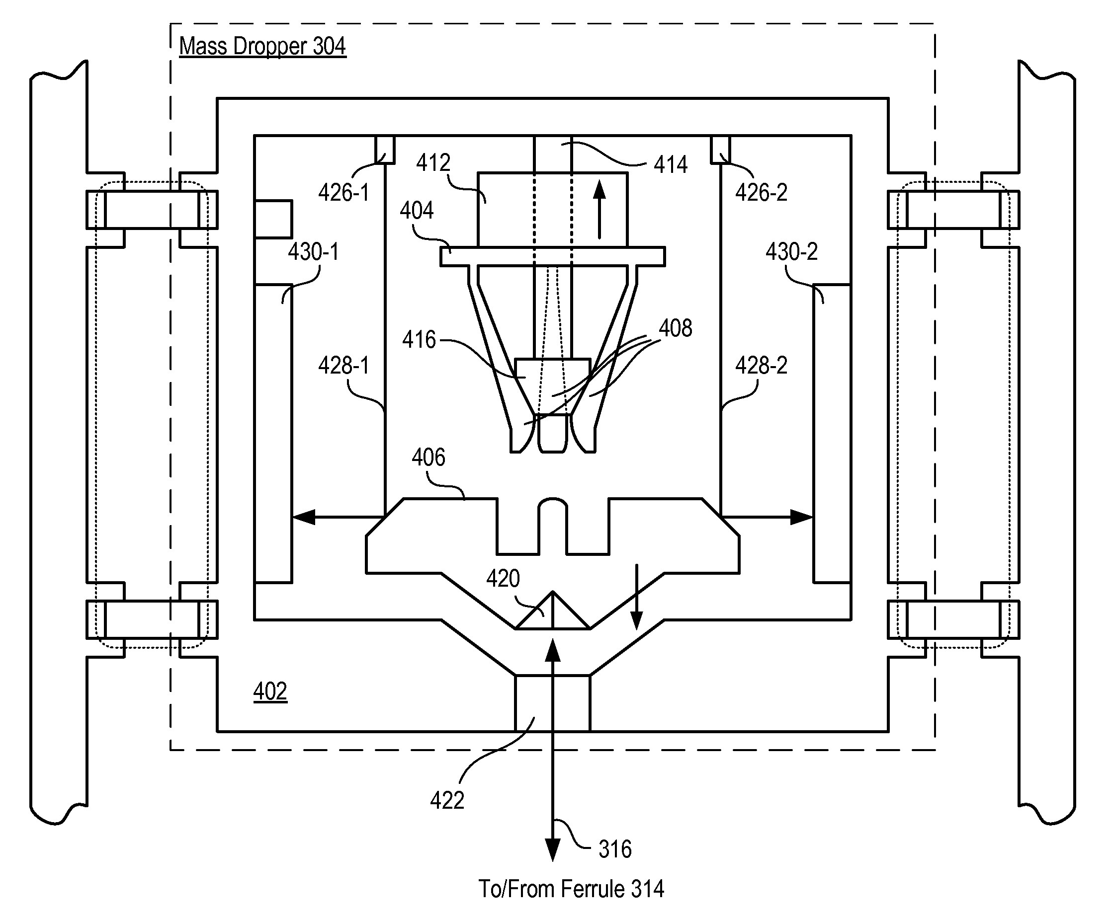
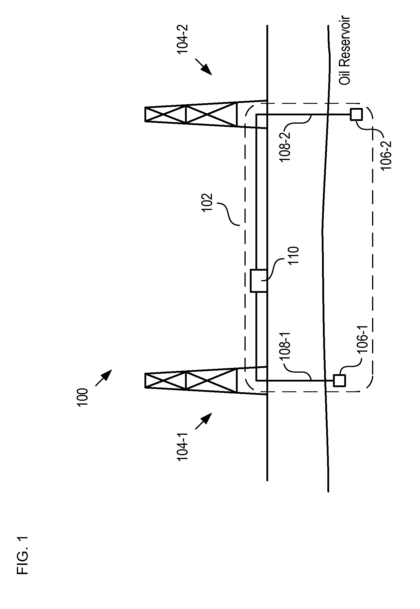
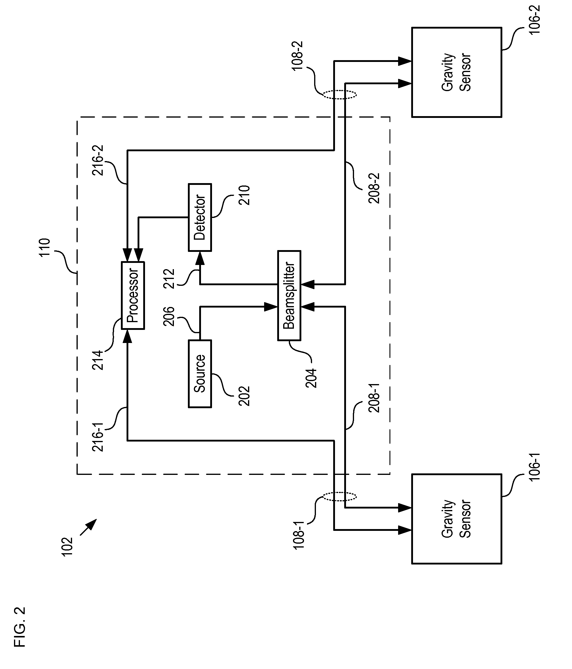
[0008]The present invention provides a differential gravity measurement system. Some embodiments of the present invention are particularly well-suited for monitoring oil flow in subterranean oil fields. In particular, the illustrative embodiment of the present invention uses a pair of optically-interrogated, free-falling test masses in a Michelson interferometer arrangement to provide a highly sensitive measurement of the difference in gravity at two locations.
[0010]Some embodiments of the invention comprise a tilt sensor that provides a feedback signal used to minimize the tilt of the mass dropper. Some embodiments of the invention comprise a rotation sensor to provide a signal based on a rotation of the test mass as it falls. This signal is used to provide a post-drop correction for mitigating the effects on the gravity sensor due to component misalignment, residual tilt of the mass dropper, effects from the rotation of the earth, and the like.

Problems solved by technology

Such extreme sensitivity, however, requires very high immunity to noise sources.
Gravimeters such as these, however, have gravity sensors that are typically too large to be inserted into a borehole of an oil well.
They are also difficult to setup and calibrate.
In addition, they are sensitive to environmental influences such as temperature and vibration.
In addition to some of the drawbacks of other prior-art gravimeters, however, noise due to shock and vibration caused by their piezoelectric launchers limits the sensitivity of these gravimeters.

Method used


Image

  • Miniature freefall mechanism
  • Miniature freefall mechanism
  • Miniature freefall mechanism

Examples


Embodiment Construction

[0019]Full-field differential gravity monitoring for modeling the fluid distribution in an oil field can be achieved by means of mapping the relative gravity across the area of an oil field. An effective method for mapping the relative gravity is the application of double differences to detect gravity changes.

[0020]In this method the differential gravity is measured at a plurality of points, referenced to a base location. These differential gravity measurements are used to develop a full-field gravity image versus time, beginning with an initial image at time, t=0. Changes in oil distribution in the oil field can be determined by comparing subsequent images either by referencing each to the initial image, or by comparing sequential images. In order to minimize random errors, each image may include an average of tens or hundreds of individual measurements between set of two points. Each set of points, comprising the differential gravity measurement between two points, can be obtained...


PUM


Abstract

A system for measuring differential gravity at two points is disclosed. In the illustrative embodiment, the system uses a pair of graspers which each repeatedly grasp, raise, and drop a test mass. The accelerations of the two free-falling test masses are monitored using optical interferometry. An output signal is provided that is based on a differential acceleration of the two test masses.

Description

CROSS REFERENCE TO RELATED APPLICATIONS[0001]The underlying concepts, but not necessarily the language, of the following case is incorporated by reference: U.S. Pat. No. 5,892,151, issued 6 Apr. 1999. If there are any contradictions or inconsistencies in language between this application and one or more of the cases that have been incorporated by reference that might affect the interpretation of the claims in this case, the claims in this case should be interpreted to be consistent with the language in this case.FIELD OF THE INVENTION[0002]The present invention relates to gravimeters in general, and, more particularly, to differential gravimeters.BACKGROUND OF THE INVENTION[0003]A differential gravimeter measures a gravity variation between two locations. In addition, multiple differential gravimeters can be used to develop a three-dimensional map of gravity. Such 3-D mapping has been proposed in order to monitor fluid flow in-situ in subterranean reservoirs, such as an oil field. I...

Claims


Application Information

Patent Timeline
Patent Type & Authority Patents(United States)
IPC IPC(8): G01V7/14
CPCG01V7/00
Inventor MEYER, THOMAS J.
Owner LOCKHEED MARTIN CORP
Learn More