Mobile snubbing system

a snubbing system and mobile technology, applied in the direction of drilling pipes, drilling rods, borehole/well accessories, etc., can solve the problems of large onsite footprint, large capital equipment costs, and large crew and operating costs, and achieve the effect of maximizing the bed area length

Active Publication Date: 2008-12-30
TEAM SNUBBING SERVICES
View PDF14 Cites 43 Cited by
  • Summary
  • Abstract
  • Description
  • Claims
  • Application Information

AI Technical Summary

Benefits of technology

[0007]An embodiment of the snubbing system of the present invention comprises a mobile transport platform having substantially all of the equipment mounted thereon as required for snubbing operations. The system comprises a snubbing structure pivotally mounted at the rear of an equipment bed of a truck. The truck comprises the equipment bed and a truck cab-over arrangement, which aids in maximizing the bed area length and also aids in providing front-loaded counterweight to the bed load. The truck is preferably a tridem drive and tandem steer with the cab in front of the steering wheels or to one side so as to meet dimensional and weight requirements for road transport.
[0008]The bed can comprise a dual rail frame, supporting the snubbing structure, ground engaging leveling and stabilization jacks, pipe racks, an indexing and kickout assembly and a pipe handler including a programmable robotic, pivoting pipe-lifting handler arm and automated tongs. Automation of the pipe handling and tongs permits the operators to be located away front the release point for well fluids or pipe. A telescoping pipe handler enables greater range of motion required to adapt between a truck of limited length and the heights required for snubbing.

Problems solved by technology

However, wellhead components are not conventionally equipped to deal with the manipulation of tubular components therethrough.
All of the required equipment results in large capital equipment costs, a large footprint onsite, extra crew and larger operating costs.
Further, conventional snubbing operations require personnel to be positioned adjacent the area for tubing connections, placing personnel at the highest risk, should there be an upset or release.

Method used


Image

  • Mobile snubbing system
  • Mobile snubbing system
  • Mobile snubbing system

Examples


Embodiment Construction

Generally

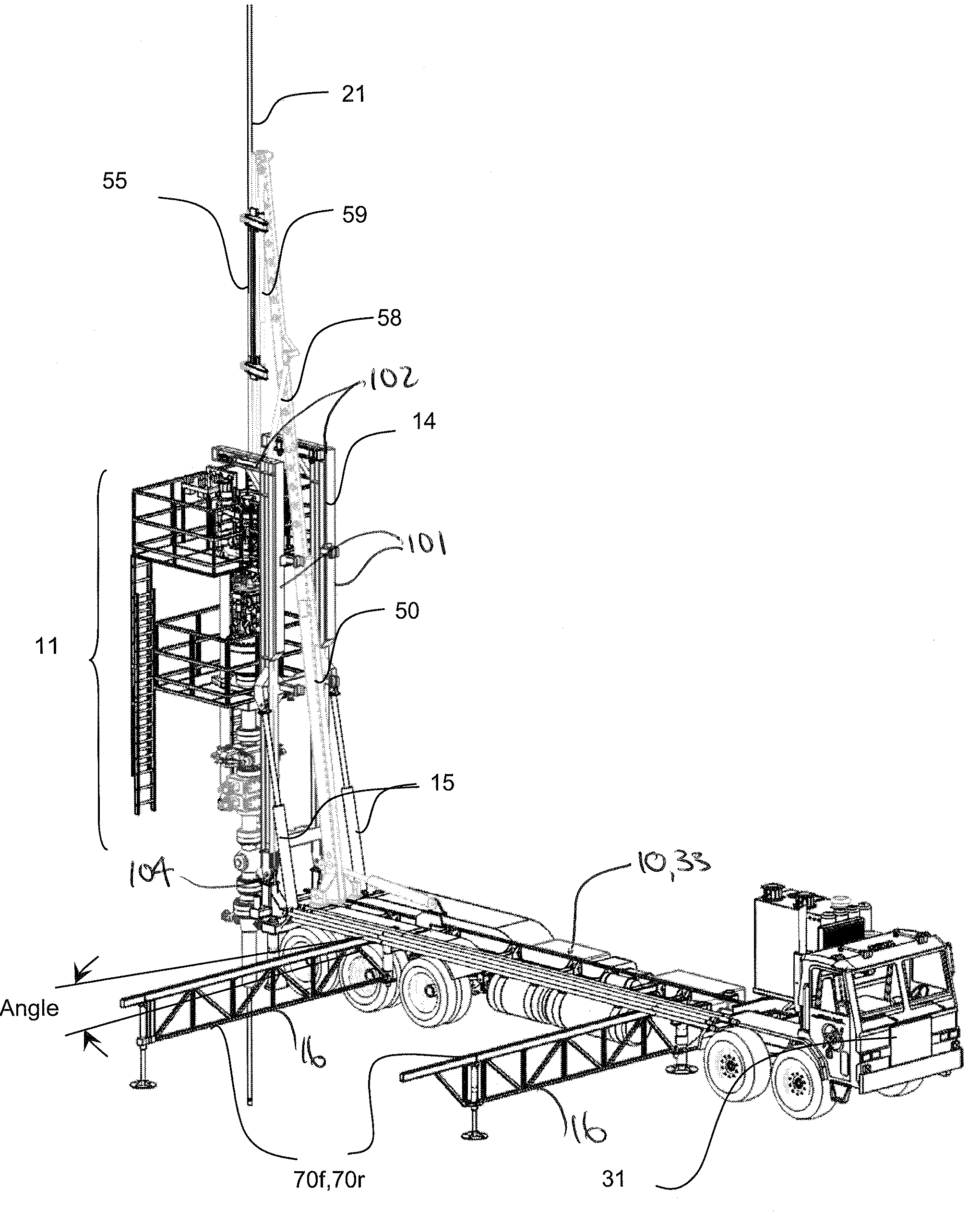
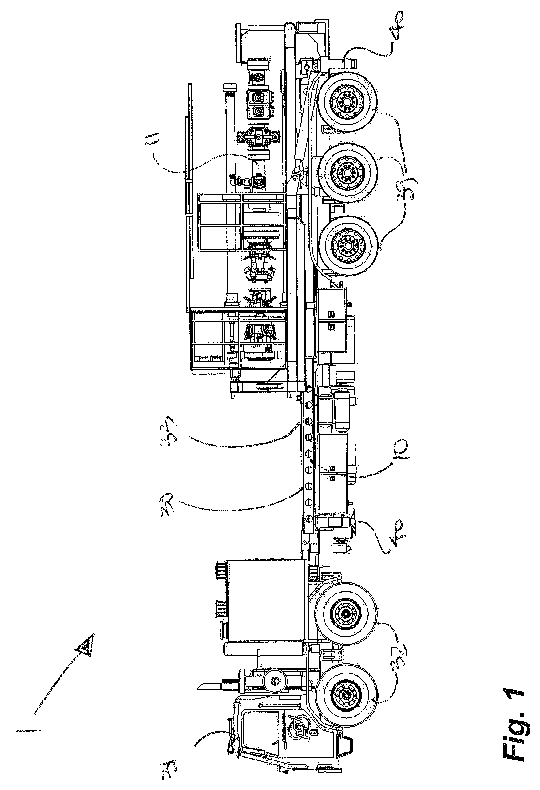
[0056]As shown in FIGS. 1 and 2, a mobile snubbing system 1 comprises a mobile platform 10 supporting a snubbing unit 11 which can be transported to a site.

[0057]With reference to FIG. 3, the snubbing unit 11, supported in a frame 14, is pivotally erected from a wellhead end or rear of the platform 10 and over a wellhead 13 using an actuator 15 acting between the frame 14 and the mobile platform 10.

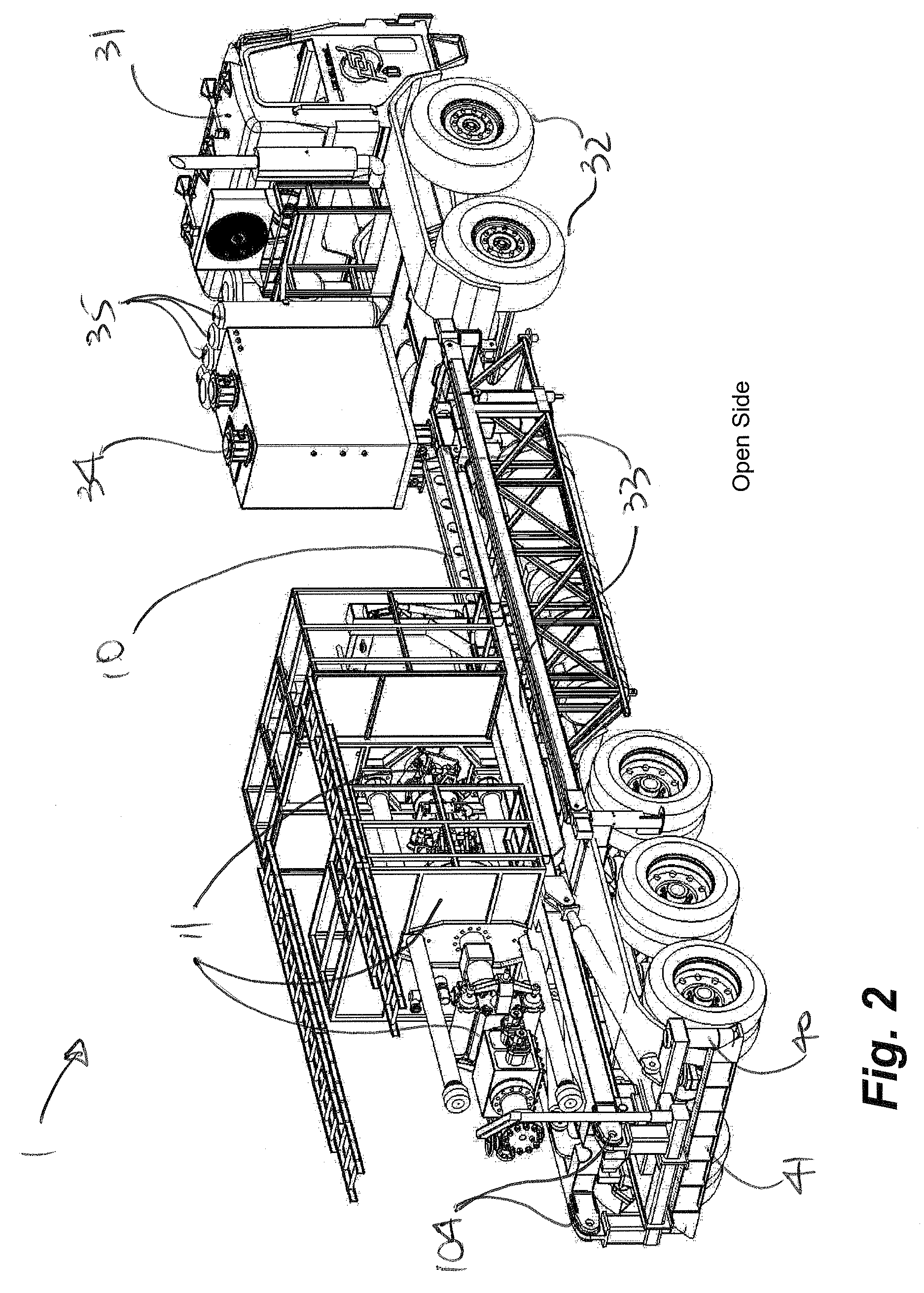
[0058]Turning to FIGS. 4A and 4B, pipe racks 16 can be pivotally extended laterally from the platform 10 for the loading and off-loading of tubulars 21 from an open side 17 of the platform 10. In FIG. 5, an integrated pipe-handler 20 can move pipe or tubulars 21 between the mobile platform 10 and the snubbing unit 11. In embodiments of the invention, the pipe-handler 20 can be telescopically actuated for adapting to length constraints imposed the mobile platform 10 and by the extended reach requirements for delivering tubulars in and out of the top of the snubbing unit 11. A know...


PUM


Abstract

A mobile snubbing system and method of operation transports a snubbing unit to a wellhead on a mobile platform. The snubbing unit is supported by a frame pivotable about a wellhead end of the platform for aligning the snubbing unit with the wellhead. A pipe handler boom is operable between a platform position for loading and off-loading tubulars at an open side of the platform and a second snubbing position for loading and off-loading tubulars at the top end of the snubbing unit. The boom can be telescopic for extending to the top of the snubbing unit and can be automated after learning tubular manipulation at the wellhead. Pipe racks can be deployable from the open side of the platform and an indexer and kicker in the platform enables loading and off-loading tubulars at the pipe handler.

Description

CROSS REFERENCE TO RELATED APPLICATIONS[0001]This application is a regular U.S. patent application claiming priority of U.S. Provisional Patent application Ser. No. 60 / 766,977 filed Feb. 22, 2006, the entirety of which is incorporated herein by reference.FIELD OF THE INVENTION[0002]The present invention relates to snubbing systems and snubbing operations requiring minimum extraneous equipment, personnel and incorporating safety aspects including BOP stack testing and repositioning personnel out of harms way.BACKGROUND OF THE INVENTION[0003]Snubbing units are known in the oil and gas industry for facilitating access to a well which is under pressure including, for example, well operations such as well completions. A snubbing unit manipulates various tubular components such as pipe, tubing, and bottom hole assemblies (BHA) in and out of a well while controlling the well under pressure. However, wellhead components are not conventionally equipped to deal with the manipulation of tubula...

Claims


Application Information

Patent Timeline
Patent Type & Authority Patents(United States)
IPC IPC(8): E21B19/08
CPCE21B7/02
Inventor FOLK, STEVE
Owner TEAM SNUBBING SERVICES
Why Eureka
Try Eureka