Position control device for moving member

a technology of moving parts and control devices, which is applied in the direction of gearing, hoisting equipment, instruments, etc., can solve the problem of limiting the position of the stopper, and achieve the effect of reducing the number of components, quick fixation, and simplifying the structure of the image forming apparatus

Active Publication Date: 2008-12-30
SHARP KK
View PDF19 Cites 6 Cited by
  • Summary
  • Abstract
  • Description
  • Claims
  • Application Information

AI Technical Summary

Benefits of technology

[0009]According to this arrangement, when the second power transmission element transmits power from a drive source to the first power transmission element, the moving member slides in an acting direction of the power. By way of example, if adopted in a shifter mechanism of an image forming apparatus, the position control device is capable of switching output positions of recording paper in conjunction with the sliding movement. In the case where the slide position of the moving member needs to be detected (in the case where the image forming apparatus is turned on or forcibly reset), power is transmitted from the second power transmission element to the first power transmission element, thereby allowing the moving member to slide in a direction of bringing the stopper closer to the second power transmission element. Later, when the moving member slides to a predetermined slide position, the projection locks the stopper and limits a position of the stopper, thereby fixing the moving member at the slide position. Namely, it is possible to control the position of the moving member by taking the slide position of the thus fixed moving member as a reference position of the moving member. Therefore, the position of the moving member can be fixed at a predetermined reference position without a special sensor for detecting the position of the moving member.
[0010]In this arrangement, the first power transmission element may be a rack which is provided along sliding directions of the moving member. The transmission part of the second power transmission element may be a sector gear which rotates in mesh with the rack and thus powers the moving member via the rack. In addition, the stopper extends orthogonally to the sliding directions of the moving member, and the projection locates away from a rotation shaft of the second power transmission element. When the moving member slides to a predetermined slide position, the stopper may move into a space between the projection and the transmission part of the second power transmission element, and the projection may establish contact with the stopper and may limit a position of the stopper.
[0013]The contact force of the projection against the stopper acts as a fixing force for fixing the moving member at the reference position. This arrangement can increase the contact force by pressing the projection against the stopper, thereby stabilizing the stop position of the moving member.
[0016]Regarding the power transmission system to the moving member, the following action may occur at the moment when the projection locks the stopper. Namely, when the projection locks the stopper and limits a position of the stopper, the transmission part of the second power transmission element maybe disengaged from the first power transmission element. To put it differently, once the projection locks the stopper, there is no power transmission from the second power transmission element to the first power transmission element, and the slide position of the moving member is limited merely by the locking of the stopper with the projection. Now, suppose that the projection has locked the stopper and power is still transmitted from the second power transmission element to the first power transmission element. Under such circumstances, if the sliding amount of the moving member due to the power transmission is not equal to the sliding amount of the moving member due to the locking of the stopper with the projection, these power transmission points will receive such a heavy load that any of the components may possibly break. In contrast, according to this solution, power transmission from the second power transmission element to the first power transmission element stops once the projection locks the stopper. As a result, this arrangement is free from such a load and can prevent breakage of the position control device.
[0018]When the image forming apparatus is turned on or forcibly reset, it needs to detect a slide position of the shifter. In this situation, if the position control device according to any of the above arrangements is applied to a shifter mechanism of an image forming apparatus, the shifter can be quickly fixed at the slide position. Hence, it is unnecessary to detect the position of the shifter with a special sensor, thereby simplifying the structure of the image forming apparatus.
[0019]Regarding a position control device for a moving member according to this invention, when the moving member moves to a predetermined position (a reference position for position control), movement of the moving member is limited by a part of the power transmission elements which have transmitted power to the moving member. To control the position of the moving member, the thus fixed position is taken as a reference position for the moving member. Hence, it is unnecessary to detect the position of the moving member with a special sensor. Consequently, while attempting to reduce the number of components and to simplify the device structure, this position control device is capable of setting the moving member at a predetermined reference position.

Problems solved by technology

When the moving member slides to a predetermined slide position, the stopper may move into a space between the projection and the transmission part of the second power transmission element, and the projection may establish contact with the stopper and may limit a position of the stopper.

Method used


Image

  • Position control device for moving member
  • Position control device for moving member
  • Position control device for moving member

Examples


Embodiment Construction

[0025]An embodiment of the invention is hereinafter described with reference to the drawings. In the following embodiment, a position control device according to an embodiment of the invention is applied to a multifunction machine which combines the functions of a copier, a printer and a scanner.

Overall Structure of a Multifunction Machine

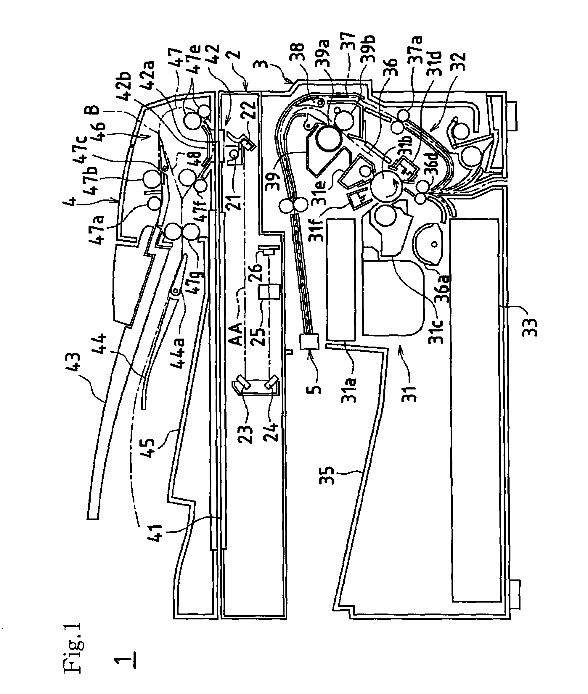
[0026]FIG. 1 schematically shows the internal structure of a multifunction machine 1 as the image forming apparatus concerning this embodiment. As shown in FIG. 1, the multifunction machine 1 has a scanner unit 2, a printer unit 3 (an image forming unit), and an automatic document feeder unit 4. Each unit is described below.

2>

[0027]The scanner unit 2 reads the image of an original and creates image data. An original is either placed on a platen 41 made of transparent glass or the like, or fed one sheet after another by the automatic document feeder unit 4. The scanner unit 2 is equipped with an exposure light source 21, a plurality of reflection mi...


PUM


Abstract

A shifter is equipped with a rack and a stopper. A transmission gear transmits power from an electric motor to the rack. A retention pin extends vertically downward from the transmission gear. When the shifter slides to an origin, the retention pin locks the stopper, which causes the electric motor to step out. On detecting the step-out of the electric motor, the position control device recognizes that the shifter has reached the origin (the reference position) and has been fixed at the position, thus setting the shifter position.

Description

CROSS-REFERENCE TO RELATED APPLICATION / PRIORITY[0001]This nonprovisional application claims priority under 35 U.S.C. §119(a) on Patent Application No. 2003-281947 filed in Japan on Jul. 29, 2003, the entire contents of which are hereby incorporated by reference.BACKGROUND OF THE INVENTION[0002]This invention relates to a device for controlling the movement position of a moving member, such as a shifter which is mounted in an image forming apparatus and which switches output positions of recording paper. In particular, this invention relates to an improvement for setting a moving member to a predetermined reference position (e.g. an origin at one end of its range of movement) with a simple arrangement.[0003]To start with, brief description is made of a conventional image forming (copying) operation by an electrophotographic image forming apparatus as represented by a digital photocopier. First, an original which is stacked on an automatic document feed tray (hereinafter referred to a...

Claims


Application Information

Patent Timeline
Patent Type & Authority Patents(United States)
IPC IPC(8): F16H19/04B65H31/00B65H33/08G03G15/00
CPCB65H33/08G03G15/6573G03G2215/00586Y10T74/19874Y10T74/1967Y10T74/18112G03G2215/00675
Inventor HIRAMOTO, YOSHIAKIKAMEI, KAYOHATANAKA, MASATSUGUYOSHIDA, SHIGERUNAKAO, MOTOKAZU
Owner SHARP KK
Why Eureka
Try Eureka