Eureka AIR delivers breakthrough ideas for toughest innovation challenges, trusted by R&D personnel around the world.

Transmission rail with guide wheels

A technology of transmission track and guide wheel, which is applied in the direction of roller table, conveyor, transportation and packaging, etc., can solve the problems that cannot be delivered to the designated place smoothly, the transported parts are easy to slip, and the transportation efficiency is low, so as to achieve simple structure and reduce Slippery and easy to operate

Inactive Publication Date: 2015-01-07
WUHU HUANQIU AUTO PARTS
View PDF7 Cites 5 Cited by
  • Summary
  • Abstract
  • Description
  • Claims
  • Application Information

AI Technical Summary

Problems solved by technology

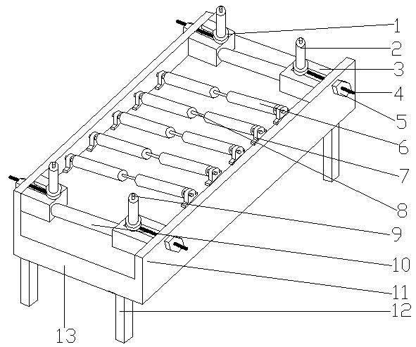
[0006] Aiming at the problems that the transportation equipment in the prior art is relatively complex and the manufacturing cost is high, while the transported parts in the simple equipment are easy to slip and cannot be delivered to the designated place smoothly, and the transportation efficiency is low, the present invention provides a transmission track with guide wheels, There is a guide plate on it, which can limit the position of the transported parts. The guide wheel mechanism can effectively adjust the width of the transported parts entering the transmission track, and then gather the originally unevenly distributed transported parts to reduce the transported parts. In the process of transportation, it is possible to deviate from the transmission track, and the two rollers are connected through the transmission shaft, which can have a certain fixing effect on the transported parts.

Method used


Image

  • Transmission rail with guide wheels

Examples


Embodiment Construction

[0023] In order to further understand the content of the present invention, the present invention will be described in detail below in conjunction with the accompanying drawings and specific embodiments.

[0024] Such as figure 1 As shown, a transmission track with guide wheels includes a bracket 13, a bearing seat 7, a roller 6, a transmission shaft 8, a guide plate 11 and a guide wheel mechanism, the bracket 13 is a rectangular frame, and the bracket 13 is along the length direction There are also guide plates 11 perpendicular to the bracket plane on both sides of the guide plate 11; N pairs of bearing seats 7 aligned left and right and equally spaced are arranged on the inner side of the guide plate 11, and N is an integer; between each pair of bearing seats 7 Two rollers 6 connected by a transmission shaft 8 are installed; the guide wheel mechanism includes a guide wheel 2, a guide wheel 1, a bolt 4, a nut 5 and a guide wheel seat 3, and the upper end of the guide wheel 1...


PUM


Abstract

The invention relates to the field of automobile equipment transportation, in particular to a transmission rail with guide wheels. The transmission rail comprises a support, bearing pedestals, rolling shafts, transmission shafts, guide plates and guide wheel mechanisms. The support is a rectangular frame; the two sides of the support are provided with the guide plates which are perpendicular to the plane of the support; the bearing pedestals which are arranged at equal intervals are arranged on the inner sides of the guide plates; two rolling shafts connected with one transmission shaft are arranged between every pair of bearing pedestals; the guide wheel mechanisms comprise the guide wheels, guide wheel discs, rolling wheels, bolts, nuts and guide wheel bases. The guide wheels are arranged at the upper ends of the guide wheel discs; the lower ends of the guide wheel discs are in contact with the guide wheel bases; one end of each bolt penetrates through a threaded hole in the corresponding guide plate to enter an inner cavity groove of the corresponding guide wheel base and is fixedly connected with the bottom of the corresponding guide wheel disc; the nuts are arranged at the other ends of the bolts to fix the bolts on the guide plates; the rolling wheels are arranged between each pair of guide wheel mechanisms. Due to arrangement of guide rails and the guide wheel mechanisms, the position of a transported part can be limited, the aim that the transported part does not fall off from the transmission rail is achieved, and therefore the transportation efficiency is improved.

Description

technical field [0001] The invention belongs to the field of automobile equipment transportation, in particular to a transmission track with guide wheels. Background technique [0002] With the rapid development of my country's economy, the area of ​​various construction plants is gradually expanding, and many equipment manufacturing needs to transport various parts to designated processing points for processing. It needs to be done at a specific point, which brings the problem of difficult delivery of auto parts. [0003] The transportation equipment in the prior art is more complicated, the manufacturing cost is high, and there are relatively simple transmission equipment, but when in use, the transported parts are easy to slip and cannot be delivered to the designated place smoothly, and the operation needs to be completed successfully with the help of manual labor . This will cause unnecessary waste of manpower and reduce production efficiency. [0004] Chinese patent ...

Claims


Application Information

Patent Timeline
Patent Type & Authority Applications(China)
IPC IPC(8): B65G13/04B65G13/11
CPCB65G13/04B65G13/11B65G2201/0294
Inventor 张天松胡仁农
Owner WUHU HUANQIU AUTO PARTS
Why Eureka
Eureka Blog
Learn More