Method for setting in-furnace tension of continuous annealing unit on line

A technology of tension setting and setting method, which is applied in the direction of furnace, furnace type, heat treatment furnace, etc., can solve the problems of no consideration of influence, difference, and large difference, so as to improve stability, maximize economic benefits, and reduce running Partial effect

Active Publication Date: 2011-04-06
SHOUGANG CORPORATION
View PDF3 Cites 24 Cited by
  • Summary
  • Abstract
  • Description
  • Claims
  • Application Information

AI Technical Summary

Problems solved by technology

The tension setting only depends on the steel type and specification, without considering the influence of incoming factors on the tension setting
In fact, even for strips of the same steel type and specification, the actual shape of different steel coils is different, and the difference is often very large, and there is even a transition from large side waves to large and medium waves. Using the same tension setting value is obviously unfavorable to the stability of the plate

Method used


Image

  • Method for setting in-furnace tension of continuous annealing unit on line
  • Method for setting in-furnace tension of continuous annealing unit on line
  • Method for setting in-furnace tension of continuous annealing unit on line

Examples


Embodiment 1

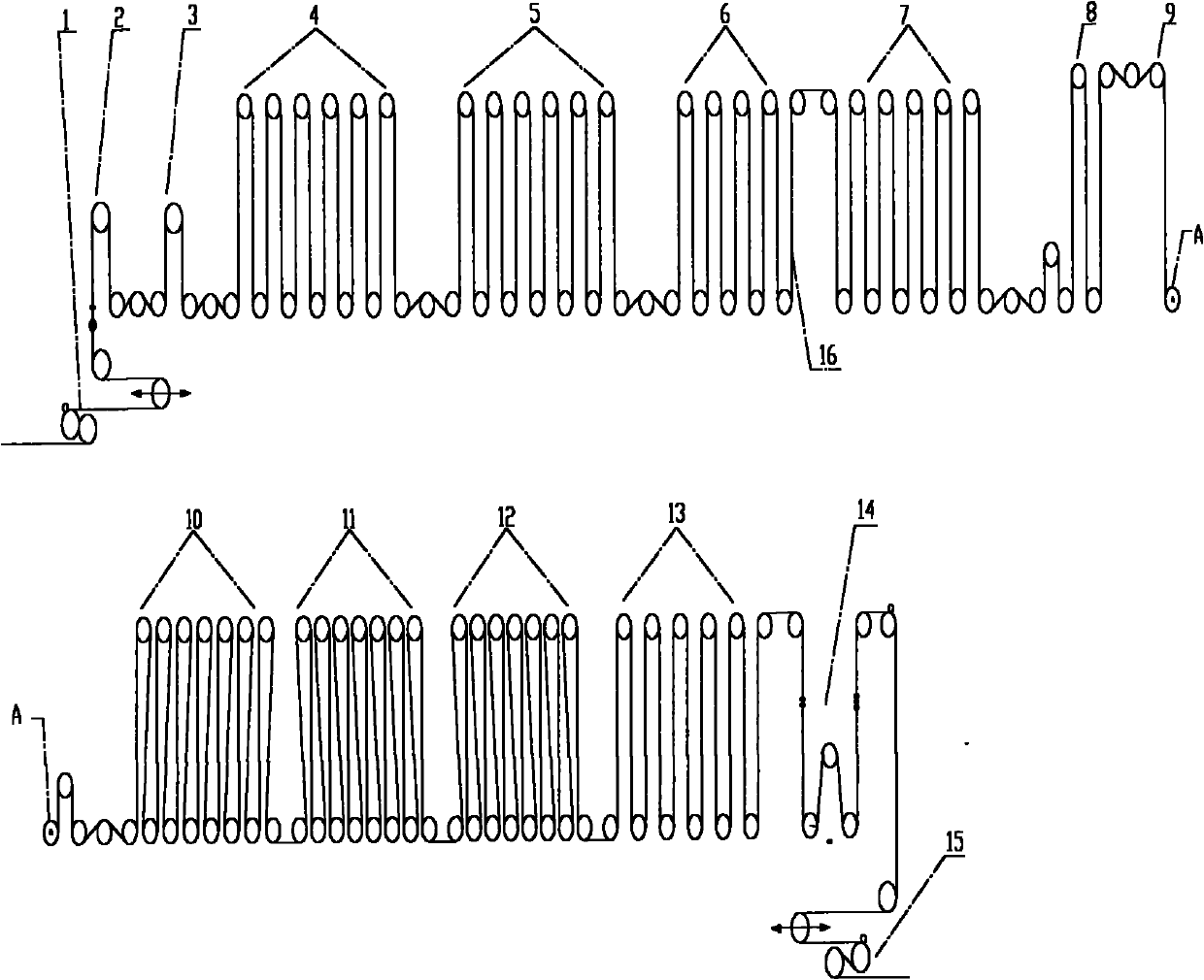
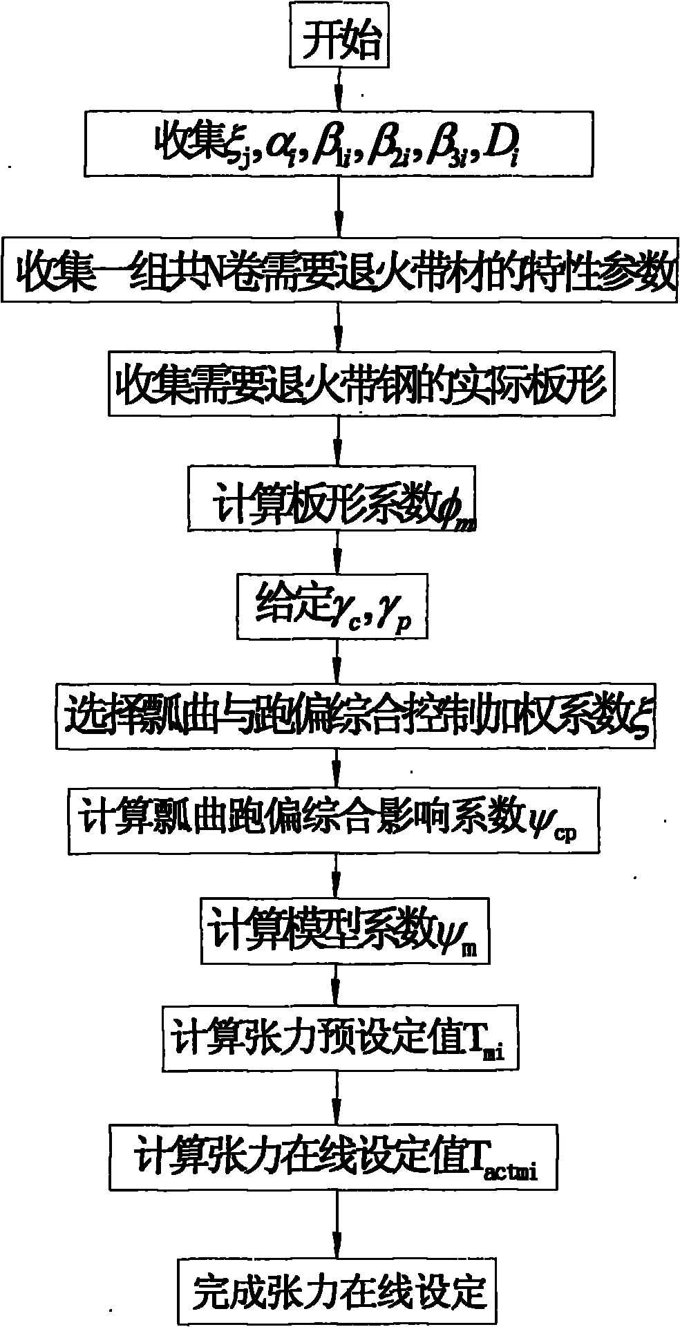
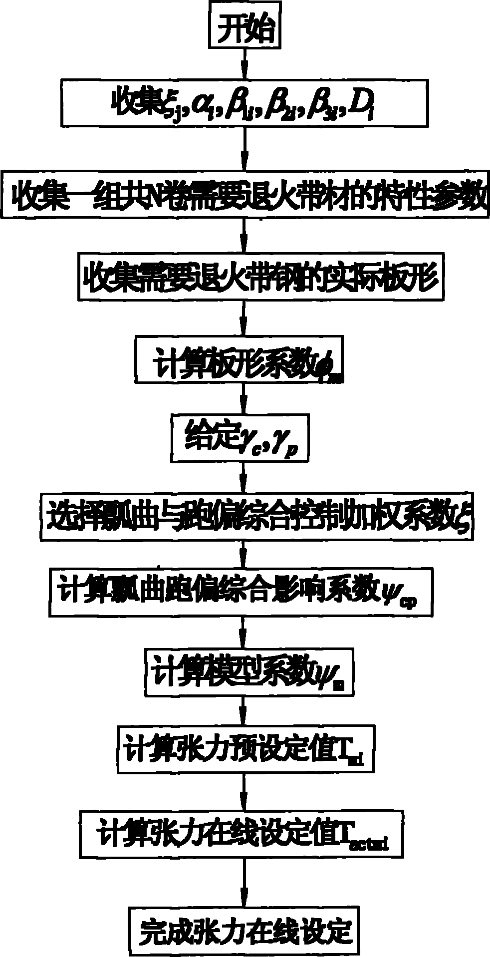
[0040] In order to illustrate the basic idea of ​​the present invention, now take a certain 1850 continuous annealing unit as an example, with the help of figure 2 To describe the online tension setting process of mild steel on a specific continuous annealing unit.

[0041] First, in step 1, the influence coefficient ξ of the equipment structure characteristics of the continuous annealing furnace is collected j (j=1, 2, L, 7), continuous annealing furnace segmental influence coefficient α i , β 1i , β 2i , β 3i (i=1, 2, L, 11), the furnace roller diameter D of each section of the continuous annealing furnace i (i=1, 2, L, 11), as shown in Table 1 and Table 2:

[0042] Table 1 Influence coefficient of furnace structure characteristics of 1850 continuous annealing unit

[0043] project

ξ 1

ξ 2

ξ 3

ξ 4

ξ 5

ξ 6

ξ 7

value

0.6082

-4.4339

12.44

-16.792

2.0589

-8.353...

Embodiment 2

[0074] In order to further illustrate the basic idea of ​​the present invention, a certain 1850 continuous annealing unit is now taken as an example, with the help of figure 2 To describe the online tension setting process of hard steel on a specific continuous annealing unit.

[0075] First, in step 1, the influence coefficient ξ of the equipment structure characteristics of the continuous annealing furnace is collected j (j=1, 2, L, 7), continuous annealing furnace segmental influence coefficient α i , β 1i , β 2i , β 3i (i=1, 2, L, 11), the furnace roller diameter D of each section of the continuous annealing furnace i (i=1, 2, L, 11), as shown in Table 1 and Table 2:

[0076] Table 1 Influence coefficient of furnace structure characteristics of 1850 continuous annealing unit

[0077] project

ξ 1

ξ 2

ξ 3

ξ 4

ξ 5

ξ 6

ξ 7

value

0.6082

-4.4339

12.44

-16.792

2.0589

-8.3535

15.52...


PUM


Abstract

The invention relates to a method for setting the in-furnace tension of a continuous annealing unit on line. The method comprises the following steps of: collecting the equipment structural characteristic influence coefficient and the sectional influence coefficient of a continuous annealing furnace and the furnace roller diameter of each section of the continuous annealing furnace; calculating a model coefficient in consideration of the influences of deviation, buckling and plate shape; calculating a preset value of the in-furnace tension of the continuous annealing unit; and putting the set value Tactmi of the in-furnace tension of the continuous annealing unit into the operation of the unit so as to finish the steps of setting the tension on line and the like. The method mainly has the advantages that: (1) by adopting a tension optimization model, the type and the specification of steel and the influence of the plate shape of an actually-supplied material are considered, namely one more dimension is considered; (2) actual equipment characteristics and an annealing process regulation can be completely combined by the tension model; and (3) in consideration of the problem of the comprehensive treatment of thermal buckling and deviation, the tension model is more flexible and more practical than a fixed table, and the model is simple and can be applied on line.

Description

technical field [0001] The invention relates to a continuous annealing production technology, in particular to an online tension setting method in a furnace of a continuous annealing unit. Background technique [0002] Annealing plays an important role in the production of cold-rolled strip steel, but initially cold-rolled strips mainly used intermittent bell annealing. Since the 1980s, due to the adoption of technologies such as rapid heating, high-temperature annealing, rapid cooling, and overaging treatment, the four processes of cleaning, annealing, smoothing, and finishing can be combined into one, at a lower cost. Products with good flatness, uniform performance and high surface cleanliness can be produced under the condition of continuous annealing, and continuous annealing has gradually developed. At present, more than a dozen countries in the world have continuous withdrawal lines, including 19 in Japan and 10 in South Korea. attached figure 1 It is a schematic d...

Claims


Application Information

Patent Timeline
Patent Type & Authority Applications(China)
IPC IPC(8): G06F17/50C21D9/56
Inventor 周利王凤琴李春光李本海朱国森刘光明周建
Owner SHOUGANG CORPORATION
Why Eureka
Try Eureka