Electromagnetic valve for controlling an injection valve of an internal combustion engine

a technology of electromagnetism and injection valve, which is applied in the direction of valve operating means/release devices, machines/engines, valves, etc., can solve the problems of reduced kinetic energy causing the bounce of the armature hitting the valve seat, so-called armature bounce of the solenoid valve, and impaired control of the fuel injection process

Inactive Publication Date: 2003-07-10
ROBERT BOSCH GMBH
View PDF2 Cites 26 Cited by
  • Summary
  • Abstract
  • Description
  • Claims
  • Application Information

AI Technical Summary

Problems solved by technology

One disadvantage of the known solenoid valves is the so-called armature bounce.
The bounce of the control valve member onto the valve seat may result in a disadvantageous vibration and/or bounce of the control valve member onto the valve seat, whereby the control of the fuel injection process is impaired.
On account of this measure, it is true tha

Method used


Image

  • Electromagnetic valve for controlling an injection valve of an internal combustion engine
  • Electromagnetic valve for controlling an injection valve of an internal combustion engine
  • Electromagnetic valve for controlling an injection valve of an internal combustion engine

Examples


Embodiment Construction

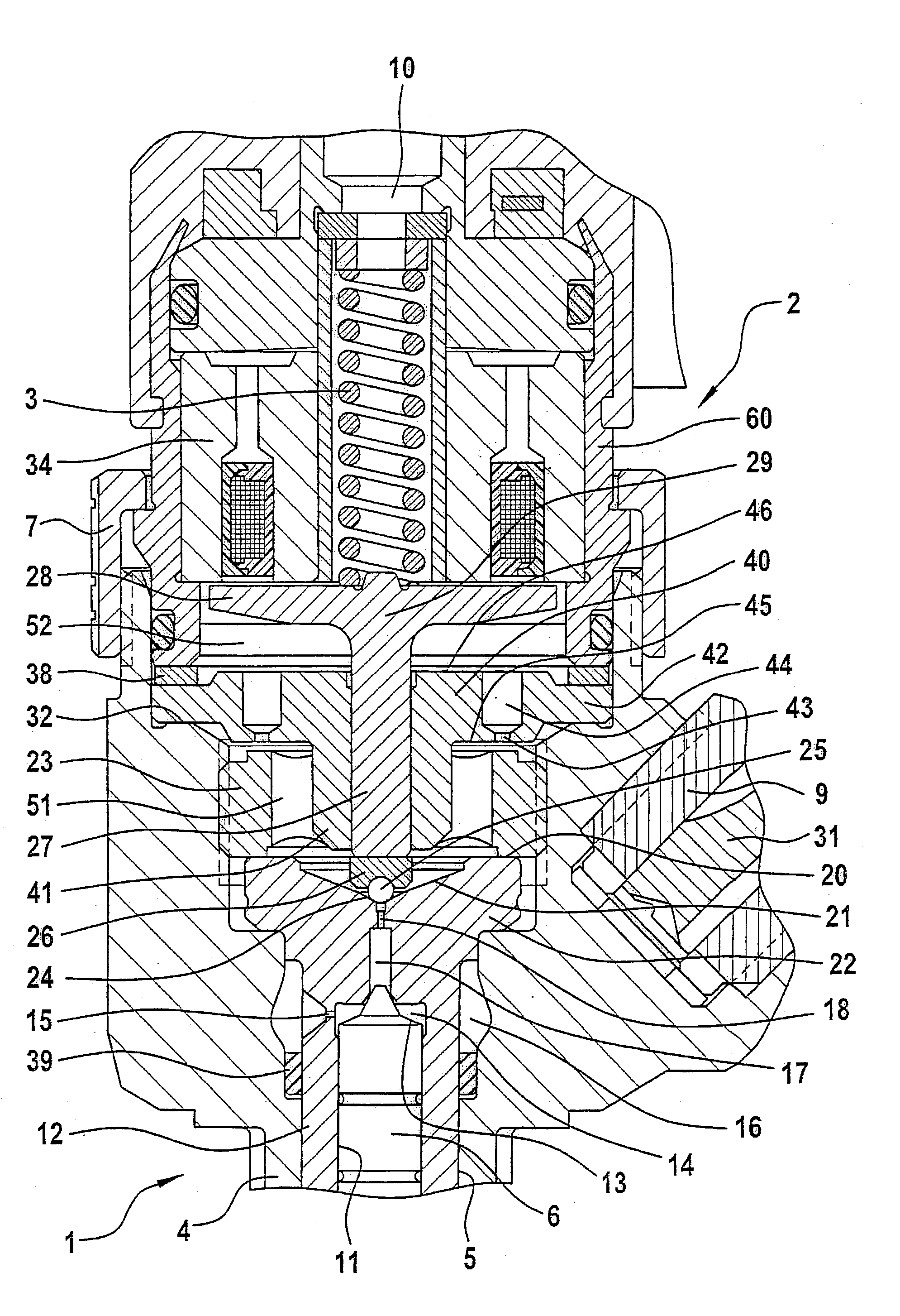
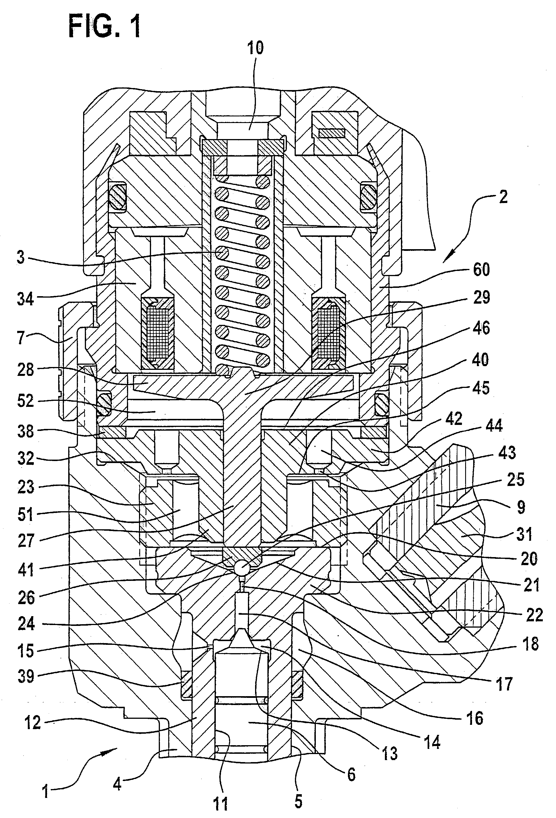
[0020] FIG. 1 shows the upper part of a fuel injector 1 which is intended for use in a fuel injection system which is equipped with a fuel high-pressure reservoir that is continually supplied with high-pressure fuel by a high-pressure booster pump. Fuel injector 1 shown has a valve housing 4 having a longitudinal bore 5, in which a valve punger 6 is positioned which acts with its one end upon a valve needle positioned in a nozzle body (not shown). The valve needle is positioned in a pressure chamber in the lower part (not shown) of fuel injector 1, which is supplied with fuel unter high pressure via a pressure bore 8. When there is an opening lift movement of valve plunger 6, the valve needle is lifted by the fuel high pressure, applied steadily to a pressure shoulder of the valve needle, in the pressure chamber counter to the closing force of a spring (not shown). The injection of the fuel into the combustion chamber of the internal combustion engine takes place through an injectio...


PUM


Abstract

The present invention relates to a solenoid valve (2) for controlling an injection valve (1) of an internal combustion engine, including an electromagnet (34), a movable armature (29), a control valve member (25,26) moved with the armature (29) and cooperating with a valve seat (24) for opening and closing a fuel discharge channel (17) of a control pressure chamber (14) of the injection valve, and a sliding piece (40) guiding the armature (29), which is positioned together with the armature (29) and the control valve member (25,26) in an armature chamber (51,52). For reducing the bounce of the armature, it is proposed that the sliding piece (40) subdivides the armature chamber into a pressure relief chamber (52) connected to a fuel low-pressure connection (10) and an hydraulic damping chamber (51), into which fuel discharge channel (17) opens out, which damping chamber may be pressure-relieved to a pressure relief chamber (52) via at least one connecting channel (44,47) provided with a throttle (43,48), the speed of the control valve member (25,26) being lowered during the closing of solenoid valve (2), before the impact on valve seat (24), by a fuel pressure cushion acting upon the control valve member (25,26) in the damping chamber (51).

Description

BACKGROUND INFORMATION[0001] The present invention relates to a solenoid valve for controlling a fuel injector of an internal combustion engine according to the generic part of claim 1.[0002] Such a solenoid valve, as is known, for example, from DE 196 50 865 A1, is used for the control of the fuel pressure in the control pressure chamber of a fuel injector, such as an injector of a common-rail fuel injection system. The fuel pressure in the control pressure chamber controls the movement of a valve plunger by which an injection opening of the fuel injector is opened or closed. The known solenoid valve has an electromagnet positioned in a portion of the housing, a movable armature, and a control valve member moved along with the armature and acted upon by a closing spring, in the closing direction, which cooperates with a valve seat of the solenoid valve and thereby controls the fuel outflow from the control pressure chamber. In the solenoid valve known from DE 196 50 865 A1 the arma...

Claims


Application Information

Patent Timeline
IPC IPC(8): F02M47/00F02M47/02F02M51/00F02M59/46F02M61/16F02M63/00
CPCF02M47/027F02M63/0017F02M2547/003F02M2200/304F02M63/0036F02M63/0022F02M63/022
Inventor HAEBERER, RAINERHORN, MATTHIASRETTICH, ANDREASHAJNOVIC, ROBERT
Owner ROBERT BOSCH GMBH
Why Eureka
Try Eureka