Method of fabricating polyurethane foam with micro pores and polishing pad therefrom

a polyurethane foam and micropore technology, applied in the direction of manufacturing tools, flexible wheels, lapping tools, etc., can solve the problems of increasing the number of layers formed on the wafer, the insufficient improvement of exposure technology alone, and the increase of the surface area of the wafer, so as to increase the process margin, simplify the fabrication process, and the effect of flexible material selection

Inactive Publication Date: 2006-02-02
DONG SUNG A & T
View PDF5 Cites 26 Cited by
  • Summary
  • Abstract
  • Description
  • Claims
  • Application Information

AI Technical Summary

Benefits of technology

[0015] To solve the above problems, an object of the present invention is to provide a method of fabricating a polyurethane foam for simplifying the fabrication processes and increasing a process margin without the generation of scratches and with greater flexibility in selecting the materials for the ingredients thereof.
[0016] Another object of the present invention is to provide a polishing pad having uniformly-sized pores and an uniform distribution of the pores, which will exhibit a high polishing efficiency and a small deviation in polishing characteristics is low among production lots.
[0017] A further object of the present invention is to provide a polishing pad having excellent properties of durability, mechanical characteristics, etc. and a method of fabricating the same, which is efficient in the improvement of the operation environment by reducing the TDI monomer amount of urethane prepolymer, as one ingredient of the composition, and which provides easily control over the process conditions due to the lengthened maintenance life of the ingredients, etc.
[0018] The present invention suppresses the generation of scratches by injecting a non-reactive gas into a foam composition without the addition of hollow sphere, to form pores in the foam by itself.
[0019] Further, the fabrication process according to the present invention is also characterized in that the formation process of bubbles is made during the mixing of two ingredient liquids, and the mixing of the two ingredient liquids is easily performed, so that the uniformity of the pore size and the distribution of the pores can be achieved which reduces the deviation in the polishing characteristics among production lots, and the maintenance life of each ingredient is increased to increase the process margin. Thus, the process is simplified, and the process expenses are reduced while the process reliability is improved.
[0020] Further, the range of the surfactants available for selection is expanded since the bubble formation process is not performed in each step of preparing the individual ingredient so as to allow various properties in the fabricated polishing pad, and the selective possibility of various ingredients is increased under various process conditions so as to increase the process margin and reduce the process expenses.

Problems solved by technology

In this view, the exposure technology for transferring patterns on a semiconductor wafer is an important process, but the improvement of the exposure technology alone is not enough to satisfy the recent demand as above.
Furthermore, the number of layers formed on the wafer is increasing along with the rapidly-developing high integration trend, and the roughness of the wafer surface is increased, which may cause difficulties in forming very fine line patterns.
During the CMP process, the polishing pad is rotated under continuously applied pressure, and herein, the micro pores in the polishing pad may be often clogged by the polishing residues generated from the semiconductor wafer being polished, and in some cases may lose their function of containing the slurry.
The polishing pad made as above has a problem of decreasing the degree of flatness of a semiconductor wafer since its surface is so soft which can easily cause due to compression, even though it has a good contact property with a semiconductor wafer and a good retention property for polishing slurry during the polishing process.
In specific, when injecting the resin composite liquid made by mixing and agitating the compounds and the hardening agent into the mold, and the hollow sphere rises up and distributes non-uniformly in the upper portion of the mixture before the resin is hardened.
Eventually, the polishing pad produced by slicing the mold in the plane direction, having a predetermined thickness, has density and hardness differences between the top portion and the bottom portion of the pad, and thus, material qualities of the pad are non-uniform, and deviation in the polishing characteristics happens among the production lots of the polishing pad.
Further, there is another problem in that, since the organic polymer hollow sphere contains low boiling point hydrocarbon in its hollow portion, and its exterior portion is composed of thermoplastic resin of acrylonytrile-vinylidene chloride copolymer or acrylonytrile copolymer, the thermoplastic resin of the pores causes scratches on the wafer surface and thus the production yield is decreased.
However, the polishing pad fabricated as described above also has a problem in that non-uniform bubbles are generated during the process of preparing the cream-like bubble dispersion liquid, and the resulting distribution of bubble size and spacing is non-uniform.
Furthermore, polishing speed and polishing efficiency are decreased, and the uniform process conditions are difficult to be controlled in the fabrication process since the polishing characteristics of the polishing pad vary depending on the locations and the production lots of a mold body.
Thus, an additional sieving process, which is employed to remove relative big bubbles and to solve the above problems, makes the fabrication processes complicated, and eventually, just the sieving process alone cannot be expected to sufficiently provide the desired results.
That is, since the retention property to maintain each ingredient in the mixture is poor and the maintenance life is short, the process margin of the fabrication process is decreased.
There exists a further problem in that the mixing of the cream-like bubble dispersion liquid with another first ingredient liquid makes it difficult to mix the mixture efficiently and easily, and as a result, the process conditions are strict and the total time for the fabrication process is increased.
Moreover, the reliability of the CMP process is also degraded since the distribution of the pores in the mixture is not uniform, and the characteristics of the polishing pad vary depending on the locations and the production lots of the molded body.
Therefore, in order to prevent the change of the property of the isocyanate terminated urethane prepolymer, there is a limitation that silicone-based nonionic surfactant containing no hydroxyl group should be selectively used, which results in a serious limitation to select the compositions for the polishing pad to meet various property requirements.
Furthermore, the silicone-based nonionic surfactant containing a hydroxyl group is more widely used, less expensive, so the above limitation in selecting the surfactant leads to higher fabrication expenses, and the process margin thereof is also deteriorated.

Method used


Image

  • Method of fabricating polyurethane foam with micro pores and polishing pad therefrom
  • Method of fabricating polyurethane foam with micro pores and polishing pad therefrom
  • Method of fabricating polyurethane foam with micro pores and polishing pad therefrom

Examples


embodiment 1

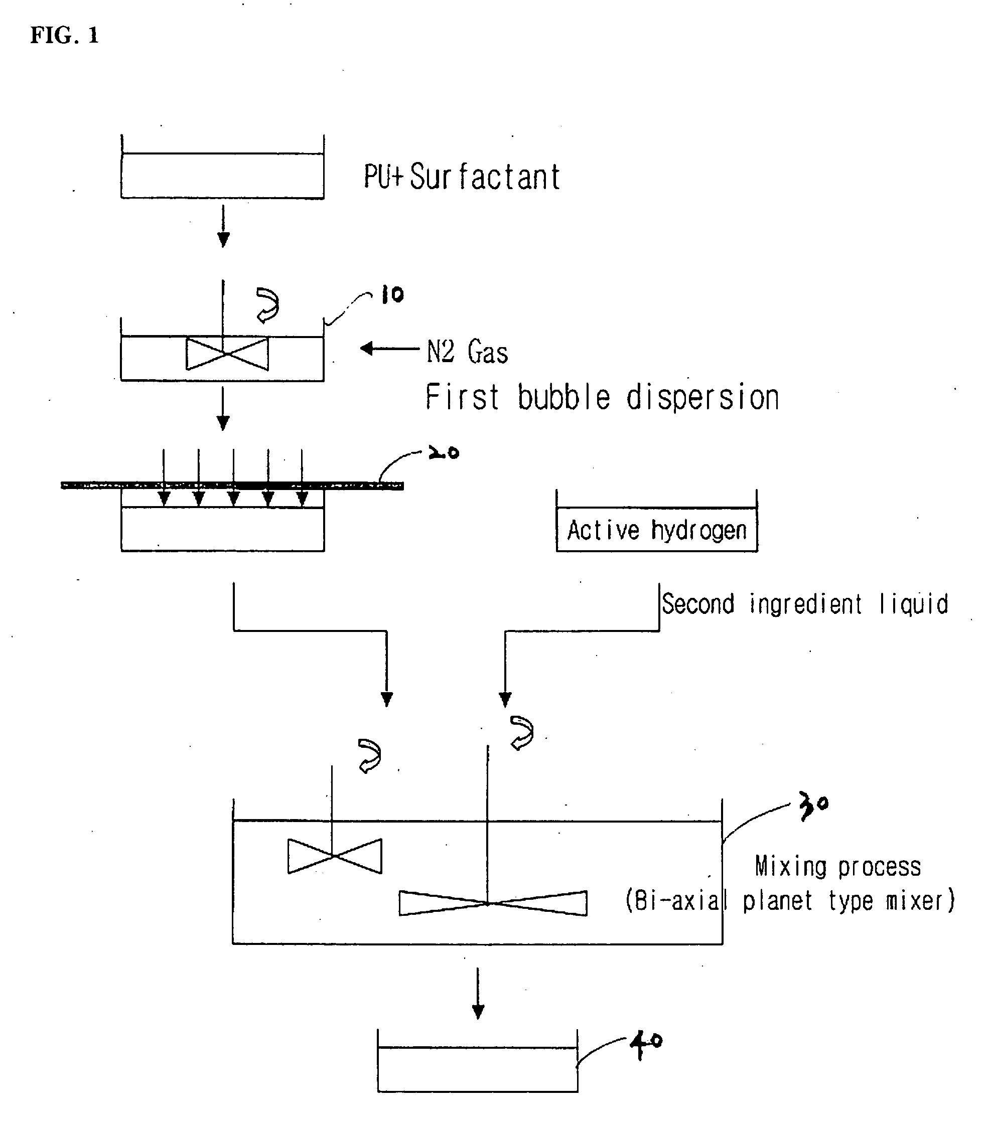
[0070] As shown in the schematic view of FIG. 2, 1 part by weight of silicone-based surfactant containing a hydroxyl group (brand name: DC-193, DOW CORNING Co., Ltd.) is mixed with 100 parts by weight of isocyanate terminated urethane prepolymer Adiprene L-325, and then, is reacted with each other at a temperature of 60□ for 2 hours. As a result, the hydroxyl group of the silicone-based surfactant becomes extinct and uniform and stabilized urethane prepolymer reaction liquid (a first ingredient liquid) is obtained. The first ingredient liquid is transferred to an air nucleation type molding machine 100, and then, non-reactive gas N2 is injected into it using a mass flowmeter 104 while injecting 24 parts by weight of MBCA (with respect to 100 parts by weight of isocyanate terminated urethane prepolymer Adiprene L-325) dissolved at a temperature of 120□ therein as a second ingredient liquid. Subsequently, the mixture is mixed and agitated by revolving paddles 108 and discharged throug...

embodiments 2 to 9

[0073] A polishing pad is fabricated by the same method as the comparative example 1, by changing the content of the surfactant, the amount of the discharged mixture, and the amount of the injected non-reactive gas, etc. with the composition ratios as shown in following Table 1, and the polishing characteristics of the polishing pad are evaluated. The results of the evaluation are shown in Table 2. As a result of examining the polishing pad produced by the embodiment 2 by using a SEM, the pores formed thereon are found to be very uniform and fine.

[0074] (see FIG. 4)

TABLE 1Composition amounts and process conditions for fabricating a polishing padControl levelActiveof massUrethaneHollowhydrogenflowmeterDischargeprepolymersphereSurfactantcompoundof mixtureAgitating(parts by(parts by(parts by(parts bynon-reactivesolutionspeedweight)weight)weight)weight)gas> (l / min)(kg / min)(rpm)ComparativeL-325 100Expancel—MOCA 25———example 12.3ComparativeL-325 100—DC-190, 1.0MBCA 26.2——3,500example 2...


PUM

PropertyMeasurementUnit
pressureaaaaaaaaaa
pressureaaaaaaaaaa
densityaaaaaaaaaa

Abstract

To provide a method of fabricating a polyurethane foam with micro pores, and a polishing pad therefrom, the method including steps of (a) adding a nonionic surfactant into at least one of a first ingredient including an isocyanate group-containing compound and a second ingredient including an active hydrogen group-containing compound, (b) agitating and mixing the mixture of the first ingredient and the second ingredient while adding a non-reactive gas thereto, (c) discharging the mixture out of a container at a predetermined rate, and (d) injecting the discharged mixture into a mold so as to form a mold body into a predetermined shape.

Description

TECHNICAL FIELD [0001] The present invention relates to a method of fabricating a polyurethane foam with micro pores and a polishing pad therefrom, and more particularly, a method of fabricating a polishing pad used for a planarization process on a semiconductor wafer by chemical mechanical polishing (CMP), and a polishing pad therefrom. BACKGROUND ART [0002] With high integration of semiconductor devices in recent years, the fineness and compactness of line patterns thereon are also rapidly increasing. In this view, the exposure technology for transferring patterns on a semiconductor wafer is an important process, but the improvement of the exposure technology alone is not enough to satisfy the recent demand as above. Furthermore, the number of layers formed on the wafer is increasing along with the rapidly-developing high integration trend, and the roughness of the wafer surface is increased, which may cause difficulties in forming very fine line patterns. Thus, there is also a st...

Claims


Application Information

Patent Timeline
Patent Type & Authority Applications(United States)
IPC IPC(8): B29C44/02B29C44/46B24D11/00C08G18/10B24B37/20B24D13/14C08G18/00C08G18/08C08G18/12C08G18/82C08G101/00C08J9/12C08J9/30C08K5/54C08K7/22C08L75/04H01L21/304
CPCB24B37/24C08G18/12C08G2101/00C08J9/30C08J2375/04C08K5/54C08G18/61C08G18/3808C08L75/04C08G18/10C08G18/82C08J9/12
Inventor LEE, KYU-DONCHA, YOON-JONG
Owner DONG SUNG A & T
Why Eureka
Try Eureka