
Wireless battery charging

Active Publication Date: 2008-12-30
KONINKLIJKE PHILIPS ELECTRONICS NV
View PDF16 Cites 194 Cited by
  • Summary
  • Abstract
  • Description
  • Claims
  • Application Information

AI Technical Summary

Benefits of technology

[0007]My invention provides such an improved apparatus and method for recharging batteries in a portable electrical or electronic device, through the use of a wireless battery charger, having an intermediate electrical energy storage device that is charged from a non-power line connected source, and discharged to recharge the battery of a portable device placed into a charge port of the wireless battery charger. The non-power line connected source may be a solar cell for converting light imp

Problems solved by technology

There are circumstances, however, under which it is impossible or undesirable to connect to a utility grid through a power cord, or where it is preferable to use another source of power for re-charging the battery.
Carrying extra disposable batteries in such circumstances is not desirable due to extra bulk and weight that must be carried both in and out of the wilderness, so that the spent batteries can be responsibly disposed of in an environmentally friendly manner.
In other instances, while it may be possible to run an electrical cord to a charger, it is inconvenient to do so.
These pagers must be kept charged, and it may not be convenient to have an electrical outlet adjacent the maitre d' station, or to run an electrical cord to a remote outlet, for charging the pagers.

Method used


Image

  • Wireless battery charging
  • Wireless battery charging
  • Wireless battery charging

Examples


Embodiment Construction

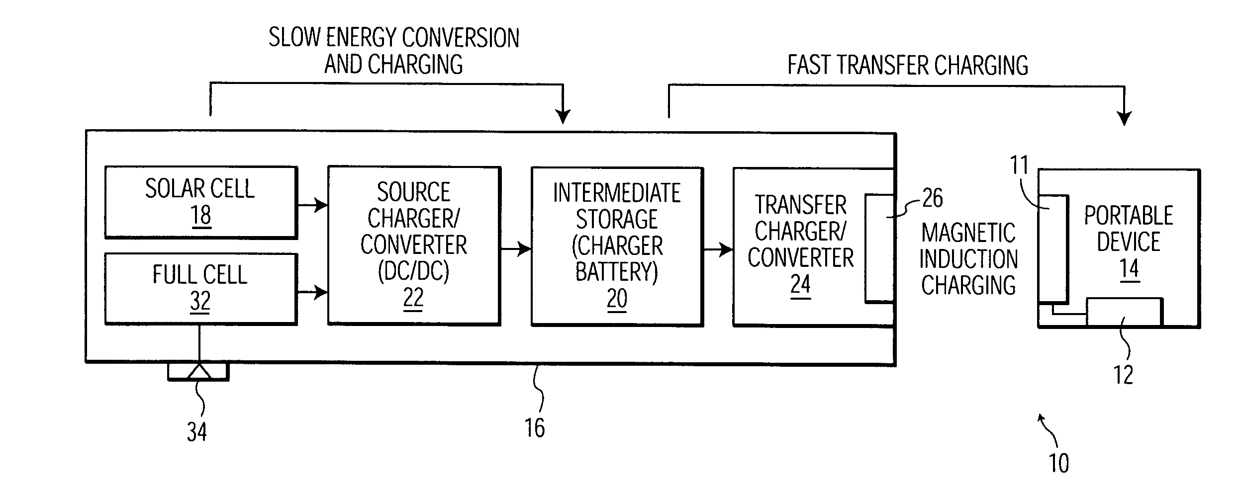
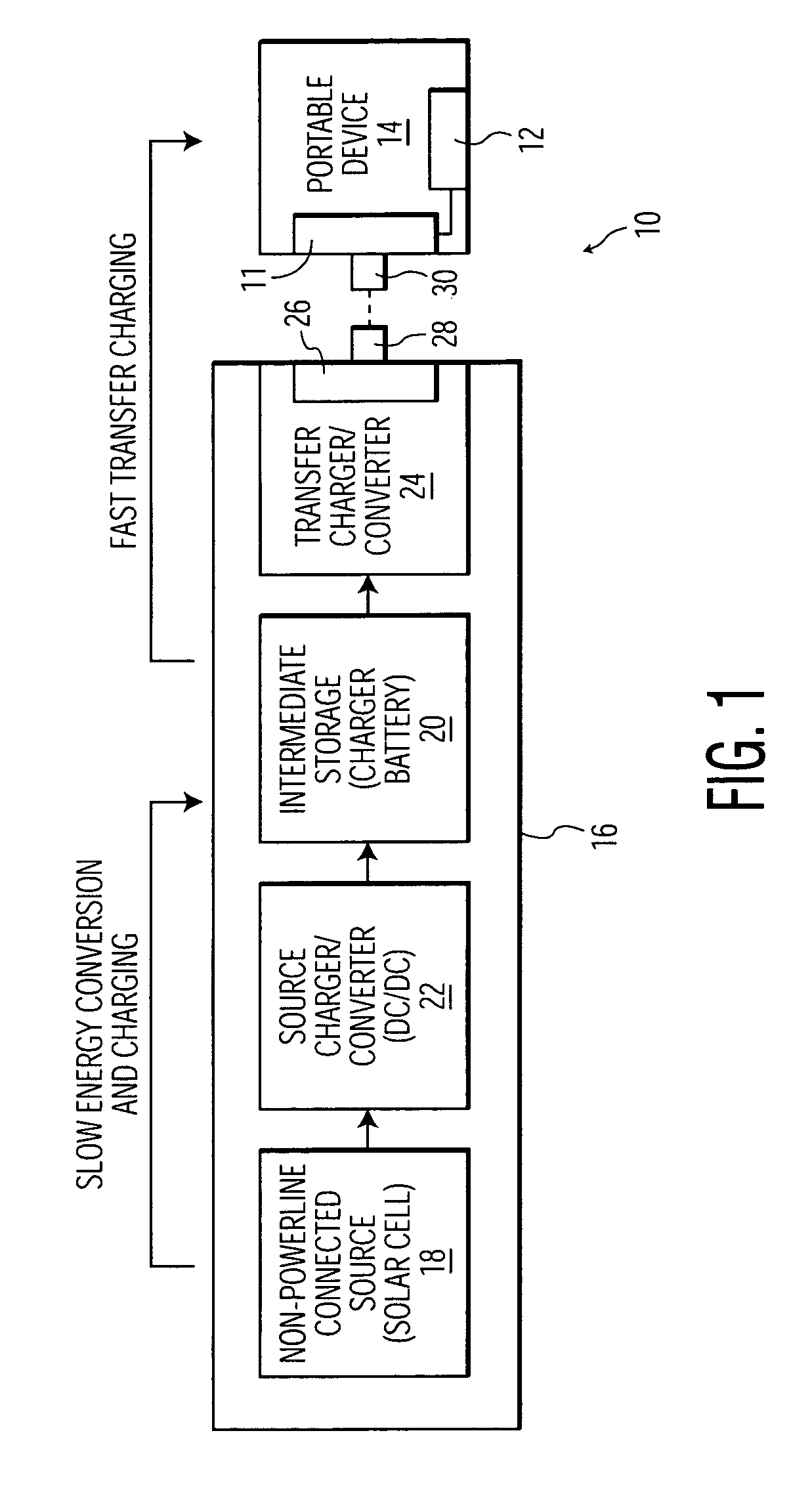
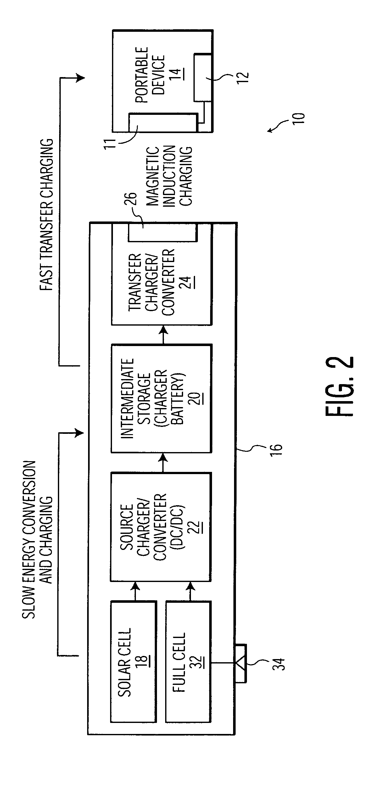
[0013]FIG. 1 is a schematic representation of a first exemplary embodiment of an apparatus 10, according to my invention, for charging a battery 12 in a portable device 14. The apparatus 10 includes a wireless charger 16 having a non-power-line-connected source of electrical charge, in the form of a solar cell 18 for converting light energy impinging on the solar cell 18 into an electrical charge, and an intermediate storage device, in the form of a charger battery 20 for storing the electrical charge. The wireless charger 16 also includes a source charger / converter, in the form of a direct-current to direct-current (DC / DC) converter 22, for charging the charger battery 20 with the electrical charge received from the solar cell 18. The wireless charger 16 further includes a transfer charger / converter 24, having a transfer circuit 26 and a charger connector 28 adapted to mate with a mating electrical connector 30 on the portable device 14, for delivering the stored electrical charge ...


PUM


Abstract

Batteries in portable electrical or electronic devices are charged, through by a wireless battery charger, having an intermediate electrical energy storage device that is charged from a non-power line connected source, and discharged to recharge the battery of a portable device placed into a charge port of the wireless battery charger. The non-power line connected source may be a solar cell for converting light impinging on the solar cell into electrical energy. The non-power line connected source may also be a fuel cell for converting a fuel into electrical energy. The wireless battery charger may also include multiple sources, such as both a solar and a fuel cell. Charging the intermediate electrical energy storage device from the non-power line connected source may take place over an extended period of time having a duration longer than the time required to charge the battery of the portable device. The wireless battery charger and portable device may include transformer elements that allow the battery of the portable device to be re-charged by magnetic induction, without the need for electrical contacts in either the charger port or on the portable device.

Description

TECHNICAL FIELD OF THE INVENTION[0001]This invention relates to charging batteries in portable electrical and electronic devices, and more particularly to charging such batteries in circumstances where it is impossible or undesirable to charge the batteries in the portable device using a battery charger connected to a power line.BACKGROUND OF THE INVENTION[0002]There are many types of portable electrical and electronic devices in use today that include rechargeable batteries, so that device can be used without a cord connecting it to a wall socket connected to a power line or grid. Examples of such cordless electrical devices include power hand tools, bathroom appliances such as electric toothbrushes and shavers, and kitchen appliances such as mixers or electric knives. Examples of portable electronic devices include cellular telephones, pagers, two-way radios, telemetry equipment, personal data assistants (PDA), computers, hand held video games, and audio entertainment devices such...

Claims


Application Information

Patent Timeline
IPC IPC(8): H01M10/46H02J7/00H02J7/35H02J17/00
CPCH02J7/0054H02J7/35H02J17/00H02J50/10H02J7/342H02J50/402H02J50/005
Inventor BRUNING, GERT W.
Owner KONINKLIJKE PHILIPS ELECTRONICS NV
Learn More