
Hybrid electric vehicle

a hybrid electric vehicle technology, applied in the field of hybrid electric vehicles, can solve the problems inability to take full advantage of capacitor storage, and battery control system, and achieve the effects of poor fuel economy, poor vehicle performance, and greater variation

Inactive Publication Date: 2007-08-07
BOWLING GREEN STATE UNIV
View PDF33 Cites 124 Cited by
  • Summary
  • Abstract
  • Description
  • Claims
  • Application Information

AI Technical Summary

Benefits of technology

Traditional electric hybrid vehicles use batteries for storing energy. However, replacing batteries with capacitors leads to poor fuel economy and reduced vehicle performance due to limitations on voltage variations. Vehicles that use capacitors instead of batteries require special controls to prevent component damage from high voltages and reduce efficiency by tapping back output. By allowing voltage to vary naturally through a range, capacitators can store more energy and allow better utilization of existing components without damaging them.

Problems solved by technology

The technical problem addressed in this patent text needs to be identified by a senior R&D person who can read it easily without adding any new information.

Method used


Image

  • Hybrid electric vehicle
  • Hybrid electric vehicle
  • Hybrid electric vehicle

Examples


embodiment

Parallel Embodiment

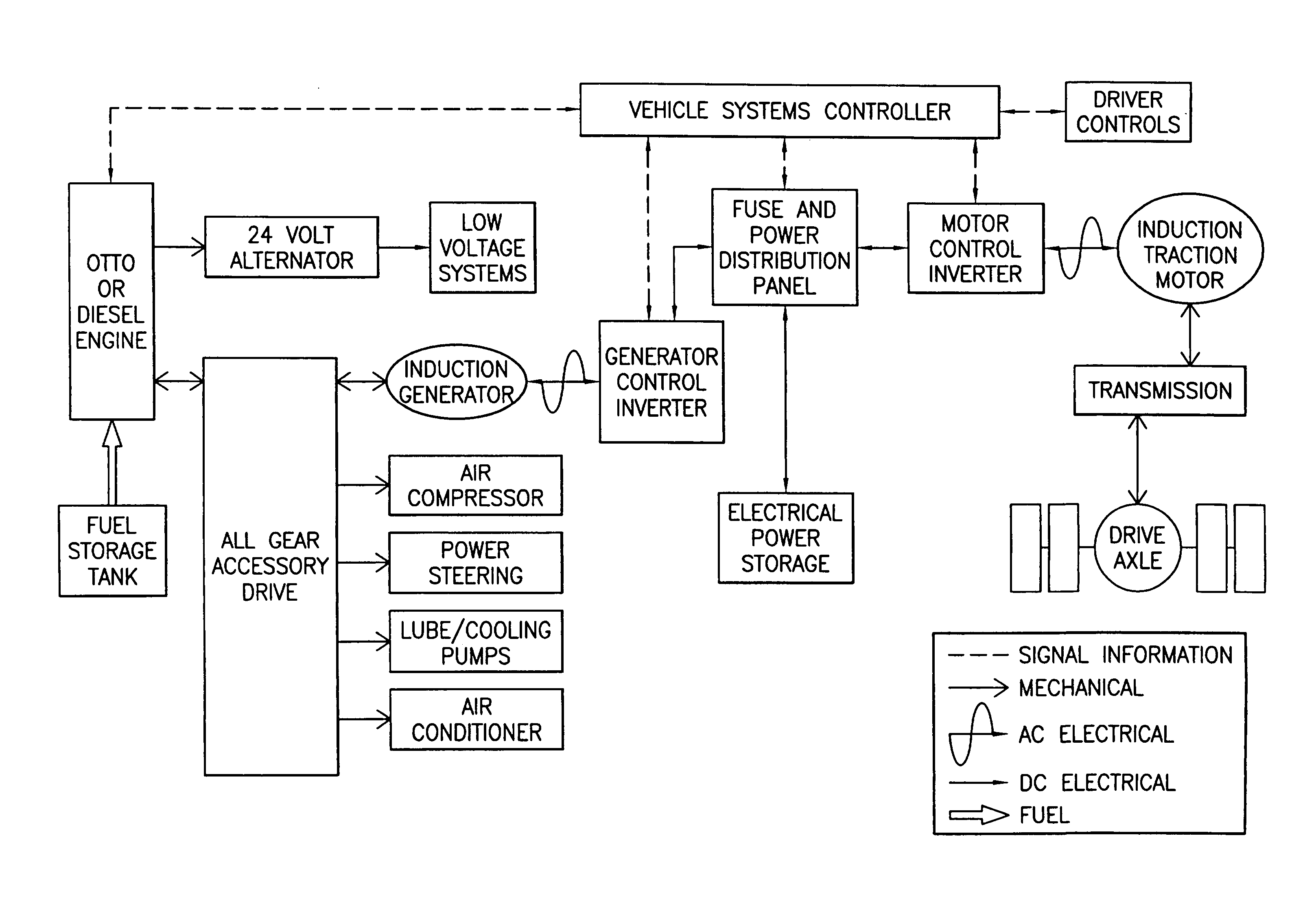
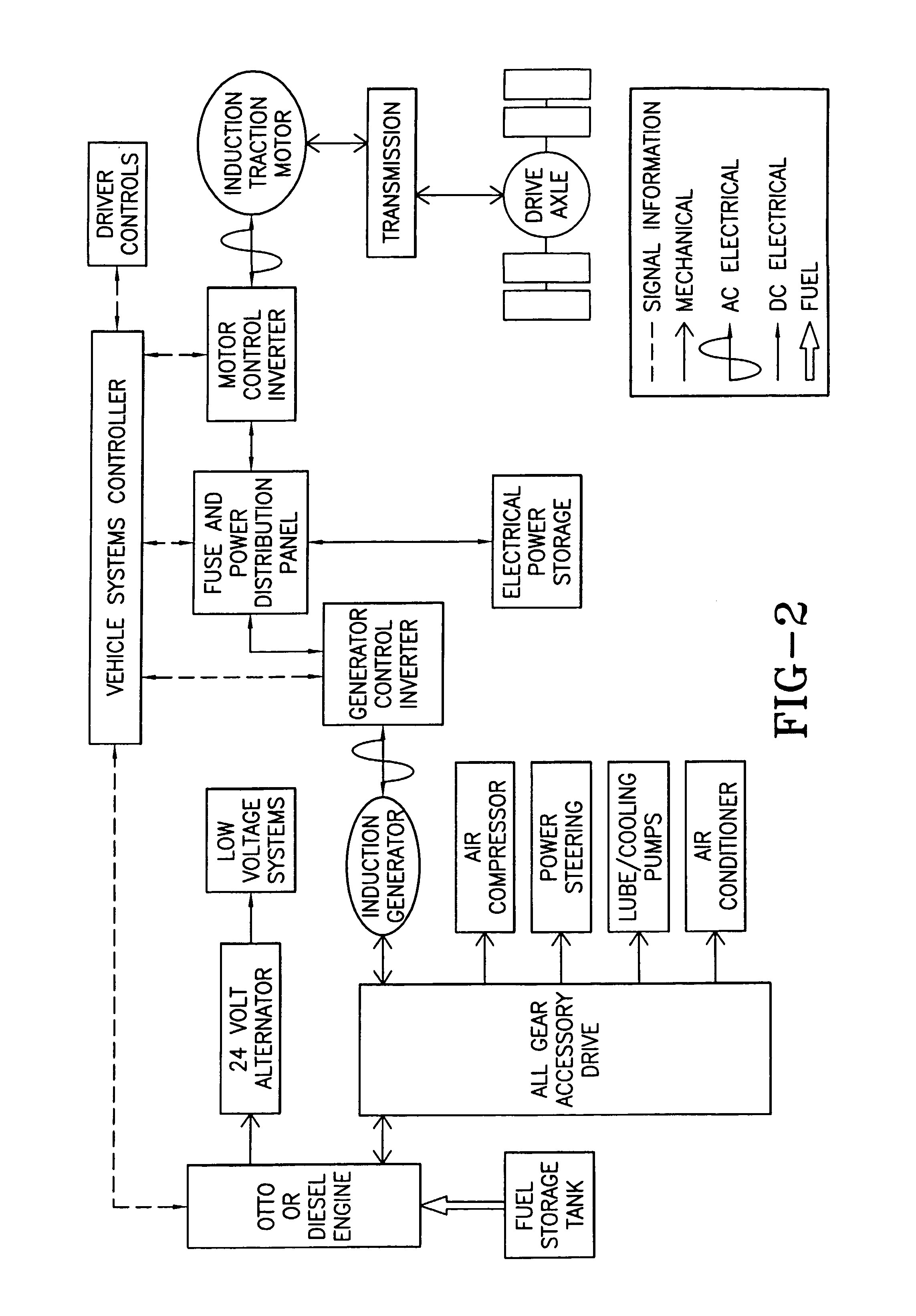
[0074]FIG. 8 illustrates one embodiment of a parallel hybrid vehicle of the present invention. In contrast to those used in a battery hybrid system, the components and control strategies of the present invention have been designed to allow for a wide fluctuation in voltage without performance loss or nuisance trip outs. The system is designed to optimize APU / PPU performance with the least amount of capacitor bank requirement. The system does not require any device between the inverter drive and capacitor bank. In its parallel form, the three major components can be easily added or retrofitted to conventional engine drive systems to hold costs down. The parallel embodiment described below may be called an engine dominated, capacitor assist, parallel hybrid system.

[0075]The hardware for the parallel system preferably consists of three major components:

[0076]One or more low inductance traction motor(s), capable of delivering rated torque and power at the low voltage ...


PUM


Abstract

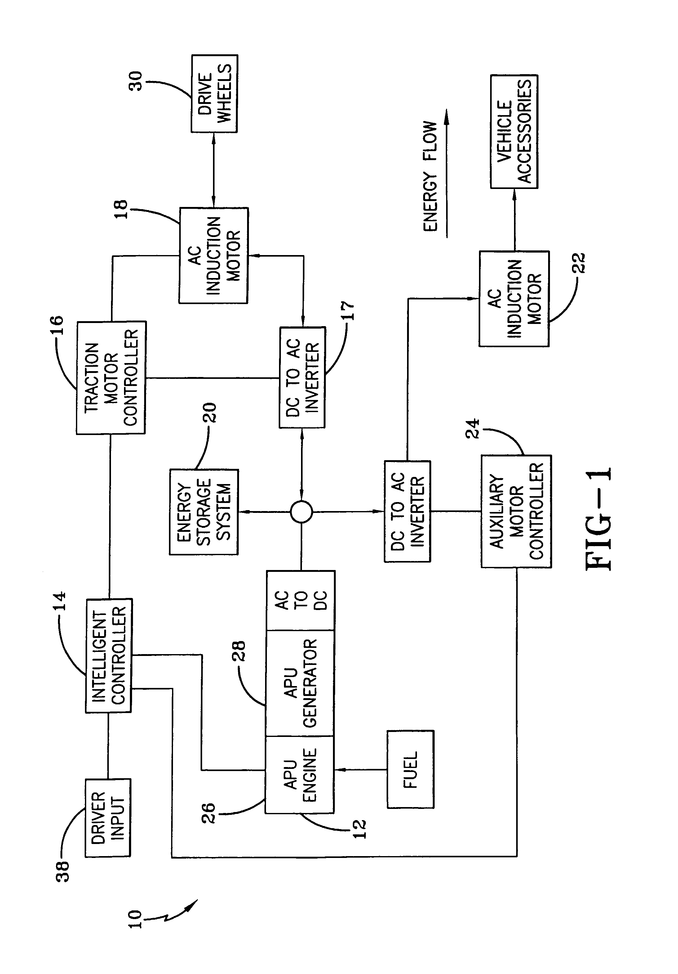
A hybrid electric propulsion system for powering a vehicle using a natural fuel engine and an electric motor. The hybrid electric vehicle is comprised of a drive train; an electric motor for driving the drive train; an auxiliary power unit (APU); an electric energy storage system electrically coupled to the electric motor; and wherein the auxiliary power unit and the electric energy storage system provide energy for powering the vehicle. An electric bus is directly connected to both the auxiliary power unit and the electric energy source and the voltage across the electric bus is substantially the same as the voltage across the electric energy source so that a change in voltage of the electric bus results in the same change to the voltage across the electric energy source. A power management controller is programmed to control output power of the power unit to maintain the energy storage system between a predetermined high voltage set-point and a predetermined low voltage set-point.

Description


Claims


Application Information

Patent Timeline
Owner BOWLING GREEN STATE UNIV
Learn More