Light brightness controller for an optical mouse
a controller and optical mouse technology, applied in the field of optical mouse, can solve the problems of inability to perform motion detection by prior optical mouse, inability to meet current standard limit,
- Summary
- Abstract
- Description
- Claims
- Application Information
AI Technical Summary
Benefits of technology
Problems solved by technology
Method used
Image
Examples
Embodiment Construction
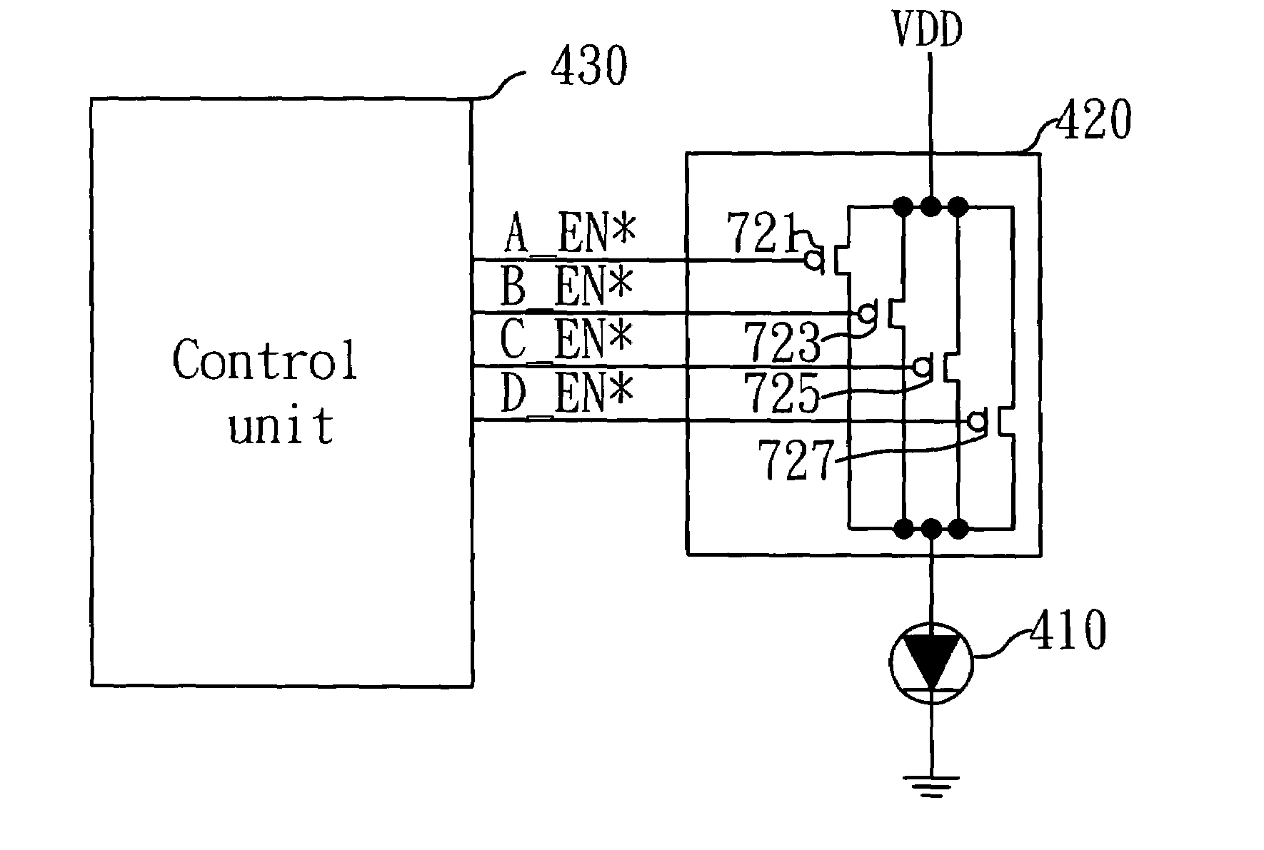
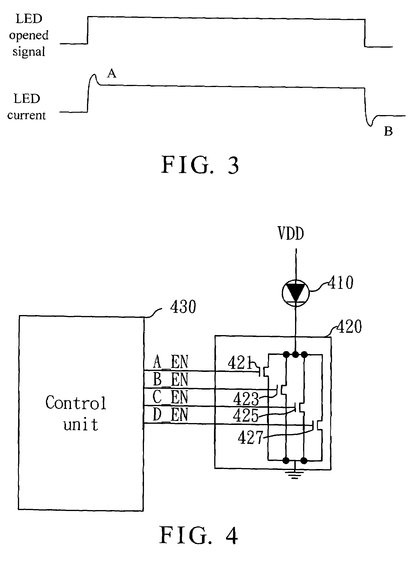
[0024]FIG. 4 is a block diagram of an embodiment of a light brightness controller for an optical mouse in accordance with the invention. In FIG. 4, the controller includes a light source 410, a current switch 420 and a control unit 430. The light source 410 is preferably an LED. The LED 410 illuminates a sampling plane of the optical mouse, and has a positive electrode connected to a high potential and a negative electrode connected to the current switch 420. The current switch 420 has a plurality of switches respectively connected to the light source 410 for providing the light source 410 with a current to flow therethrough as one of the switches is turned on. The control unit 430 is connected to the current switch 420 for controlling the current flowing through the light source 410 by controlling the switches on and off.
[0025]As shown, the switches consist of NMOSs 421, 423, 425 and 427. The NMOSs 421, 423, 425 and 427 respectively have a drain connected to the negative electrode ...
PUM
 Abstract
Description
Claims
Application Information
 - R&D
- Intellectual Property
- Life Sciences
- Materials
- Tech Scout
- Unparalleled Data Quality
- Higher Quality Content
- 60% Fewer Hallucinations
Browse by: Latest US Patents, China's latest patents, Technical Efficacy Thesaurus, Application Domain, Technology Topic, Popular Technical Reports.
© 2025 PatSnap. All rights reserved.Legal|Privacy policy|Modern Slavery Act Transparency Statement|Sitemap|About US| Contact US: help@patsnap.com


