Fluidic device

a technology of fluid flow and fluid flow, which is applied in the field of fluid flow device, can solve the problems of reducing the flow velocity, and affecting so as to achieve the effect of reducing the resistance of fluid flow and strengthening or enhancing the flow of fluid through the dus

Active Publication Date: 2009-01-06
HITACHI IND EQUIP SYST CO LTD
View PDF12 Cites 11 Cited by
  • Summary
  • Abstract
  • Description
  • Claims
  • Application Information

AI Technical Summary

Benefits of technology

[0020]With such the structure as was mentioned above, the resistance is lowered against fluid within the connector duct, and the flow passing within the dust is strengthened or enhanced, therefore there can be achieved the fluidic device being able to oscillate with stability, if being made small in the sizes thereof.

Problems solved by technology

First, because a portion of energy that the fluid has is used as energy for driving the mechanism, therefore a loss of energy is increased, thereby lowering the flow velocity;
Second, due to movement of the mechanism, there is a possibility of generating dusts, in particular, from the bearing thereof, etc., thereby contaminating the fluid, therefore it is difficult to apply it into a facility for producing drags, foods, or into a clean room of high cleanness, etc.
Third, maintenance is indispensable for the mechanism;
Fourth, a number of parts of the nozzle is increased for building up the mechanism, and also costs rise up due to the complicated manufacturing steps thereof; and
Fifth, due to the problems, i.e., durability of the mechanism portion or the like, such as the bearing, etc., it is difficult to be applied into the conditions, such as, a fluid of high temperature or low temperature, a fluid of strong acid or strong alkaline, also into a gas contaminated with dusts and a water of rivers containing waste therein; i.e., it is restricted on the fluid to which the device can be applied.
Namely, for producing the flow amount with a little pressure difference, it is necessary to lower the flow resistance within the connector duct, and then the connector duct increases in the area of flow passage therein, therefore there is a problem that the device or apparatus comes to be large in the sizes, as a whole.

Method used


Image

  • Fluidic device
  • Fluidic device
  • Fluidic device

Examples


Embodiment Construction

[0049]Hereinafter, embodiments according to the present invention will be fully explained by referring to the attached drawings.

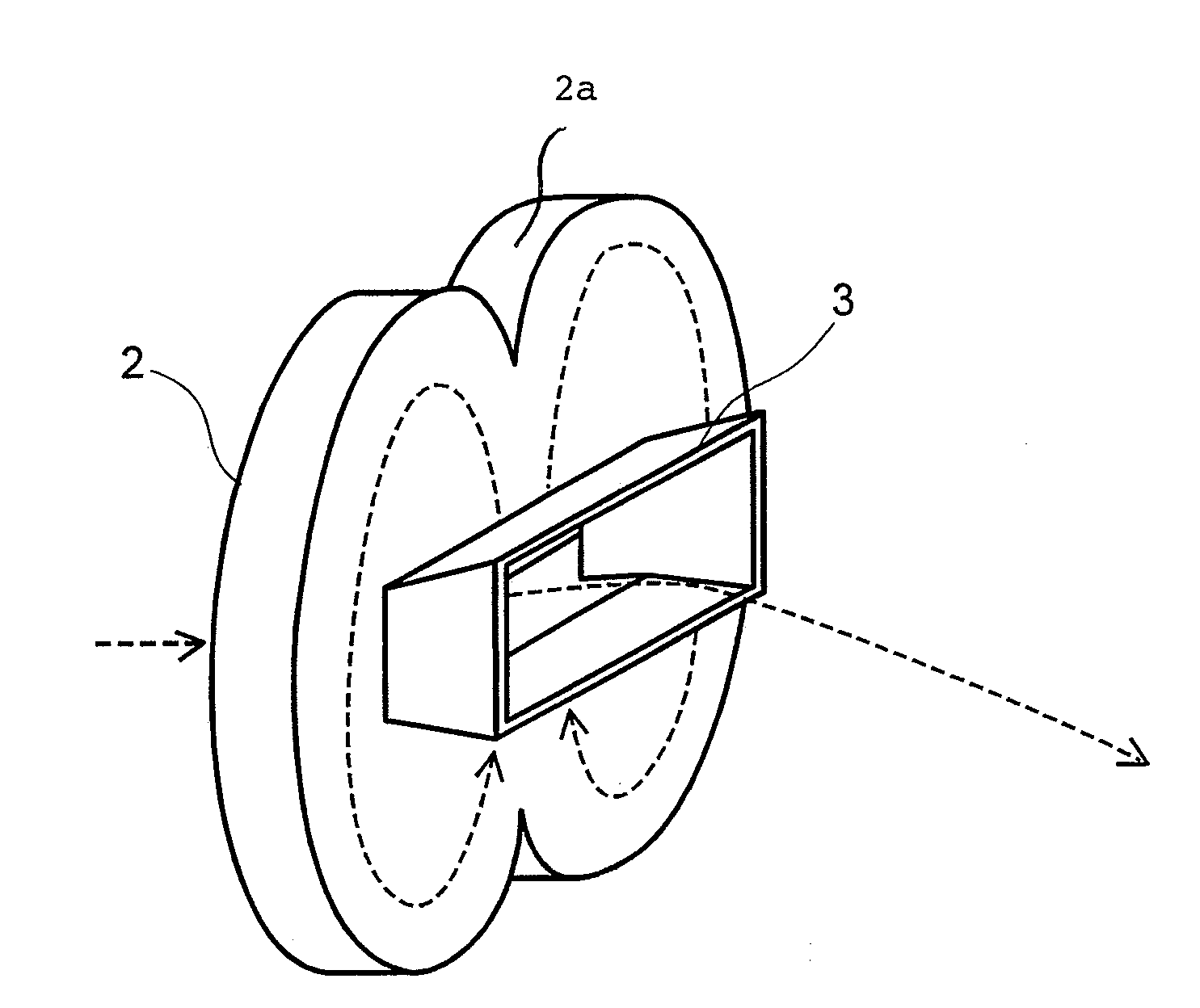
[0050]FIG. 1 is a perspective view of a fluidic device, according to one embodiment of the present invention.

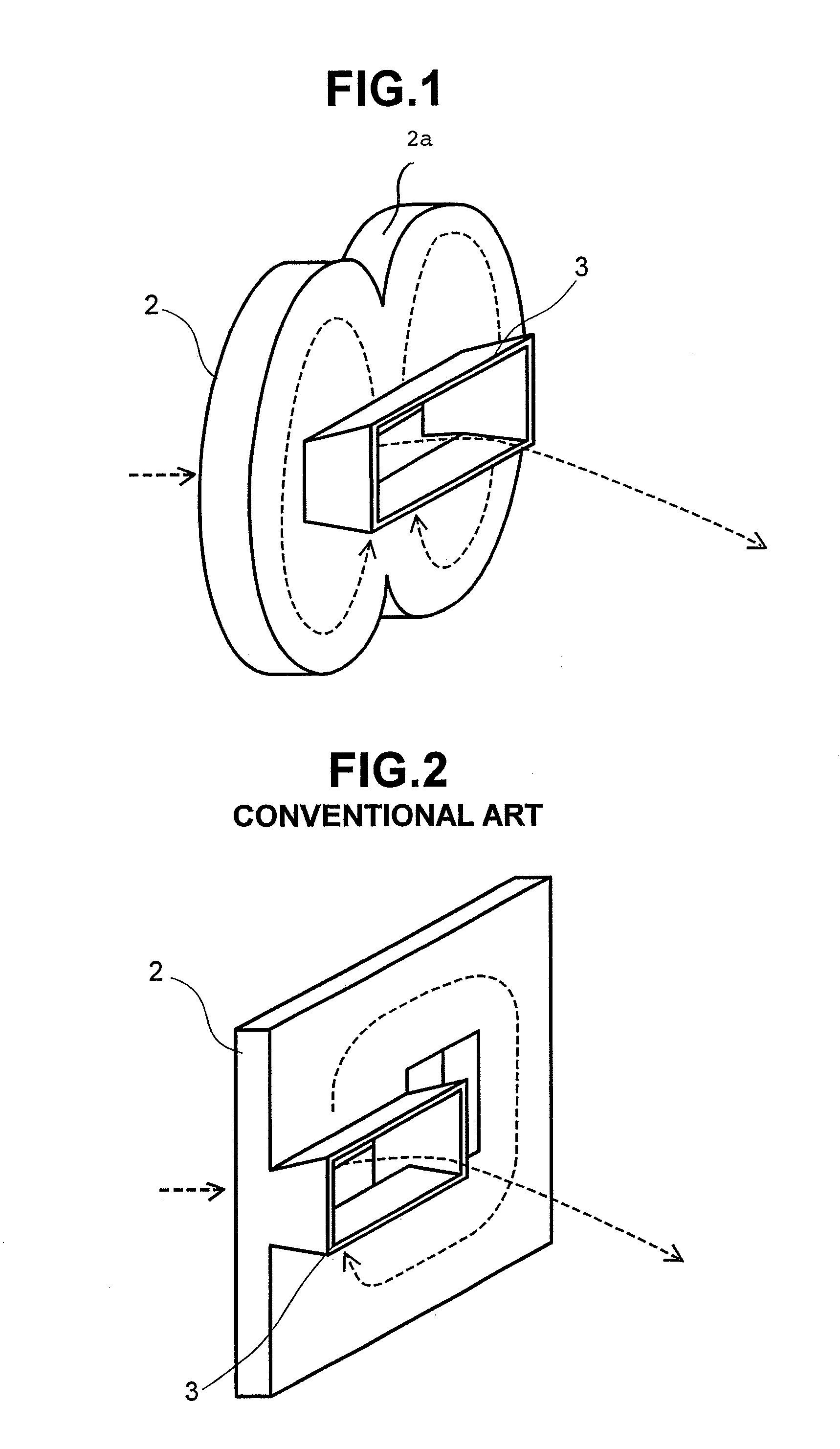
[0051]FIG. 2 is a perspective view for showing a conventional fluidic device, which is described in the Non-Patent Document 1 mentioned above.

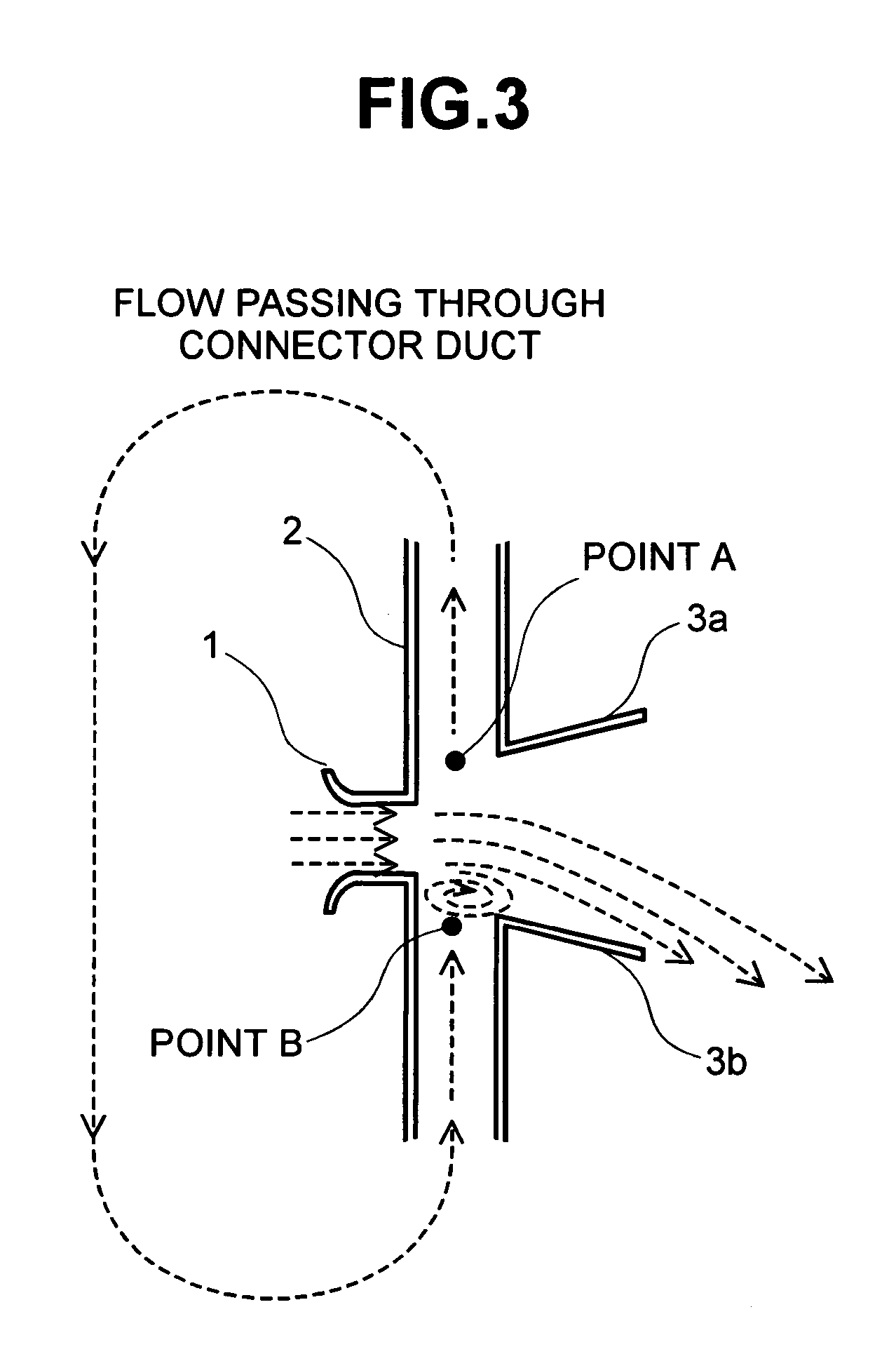
[0052]FIG. 3 is a cross-section view for explaining those nozzle portions.

[0053]In those FIGS. 1, 2 and 3, the fluidic device is constructed with a fluid inflow opening 1, a connector duct 2 having a wind guiding plate 2a in the form of a curved surface, and a fluid jet nozzle 3 (in FIG. 3, an upper plate of the nozzle is indicated by 3a and a lower plate by 3b, respectively, for convenience). Broken lines in the figure indicate flows of the fluid.

[0054]Operation of the present fluidic device will be shown below.

[0055]The fluid flowing into from the fluid inflow opening 1 comes across the connector duct 2, and ...


PUM


Abstract

For achieving a fluidic device, being able to be made small in sizes, comprising a fluid inflow opening 1, a connector duct 2, and a fluid jet nozzle, wherein the connector duct 2 is constructed with curves, and is further constructed with two (2) pieces of flow passages, being symmetric on both sides. Constructing the connector duct with the curves reduces resistance of fluid within the duct, and further dividing the connector duct into two (2) parts in both side enhances the flows at confluent point in the duct (increase of the flow velocity).

Description

BACKGROUND OF THE INVENTION[0001]The present invention relates to an apparatus, such as, a sprinkler for fluctuating or changing the velocity of fluid flowing out from a nozzle at a specific cycle or period, for example.[0002]In general, for the purpose of changing the velocity of fluid flowing out from a nozzle, the velocity is controlled by changing the configuration of the flow passage in the vicinity of the nozzle, there by changing an orbit of the fluid jetting out from the nozzle. In particular, as the structure for controlling the fluid, without using an electric driving mechanism, etc., a mechanism is used, such as, a nozzle for use of a jet bath (see Patent Document 1) or a pulse air jet generating device (see Patent Document 2), for example.[0003]Each of those comprises a mechanism to be driven through hydraulic power in the vicinity of the position of flow-out in the nozzle, where in the configuration of the flow passage is changed through movement of the mechanism with a...

Claims


Application Information

Patent Timeline
Patent Type & Authority Patents(United States)
IPC IPC(8): B05B1/08B05B1/34B05B1/00B05B1/02
CPCB05B1/005B05B1/08Y10S239/03Y10T137/2104Y10T137/2185B05B1/02
Inventor MUKAI, HIROSHIHONMA, KEIICHIHONDA, TAKESHIKIMIYA, TETSUO
Owner HITACHI IND EQUIP SYST CO LTD
Why Eureka
Try Eureka