Vehicle body structure

a technology for vehicles and body parts, applied in the direction of roofs, transportation and packaging, vehicle arrangements, etc., can solve the problems of not contributing much to the improvement of the strength not easy to achieve the above-described reinforcement b>, and the effect of deformation suppression is not easy to achieve. , to achieve the effect of reliably suppressing the deformation of the vehicle body, simple structure and efficient transfer of impact energy

Inactive Publication Date: 2009-01-06
MITSUBISHI MOTORS CORP
View PDF26 Cites 10 Cited by
  • Summary
  • Abstract
  • Description
  • Claims
  • Application Information

AI Technical Summary

Benefits of technology

[0018]Therefore, according to the vehicle body structure of the present invention, at the time of a collision from behind, it is possible, with a simple structure, to efficiently transfer impact energy to a center pillar via a reinforcement. As a result, the impact energy is converted to kinetic energy which will give the vehicle acceleration, so that it is possible to reliably suppress the deformation of the vehicle body. Further, the vehicle body structure of the present invention is advantageous in that the vehicle body deformation is suppressed irrespective of the positional relationship between the rear pillar and the cross member. In consequence, it is possible to suppress the relative displacement of a fuel tank, so that the fuel tank is protected from damages thereto.

Problems solved by technology

In addition, in the above-described art, since the reinforcement 104 is provided for the purpose of ensuring rigidity of the vehicle body, it does not contribute much to the improvement of the strength of the vehicle body.
Thus, it is not easy for the above-described reinforcement 104 to suppress a considerable deformation caused when a large load is applied in a collision from behind the vehicle.
When the reinforcement 104 is used to suppress the vehicle body deformation, there is a problem that the effect of deformation suppression greatly depends on a positional relationship between the rear pillar and the cross member.
Thus, when load is input from behind (at the time of a collision from behind the vehicle), it is impossible to sufficiently suppress the forward deformation of the wheel house.
Thus, moment, not compressive load, is input to the first reinforcement, so that it is impossible to suppress the deformation of the vehicle body.

Method used


Image

  • Vehicle body structure
  • Vehicle body structure
  • Vehicle body structure

Examples


Embodiment Construction

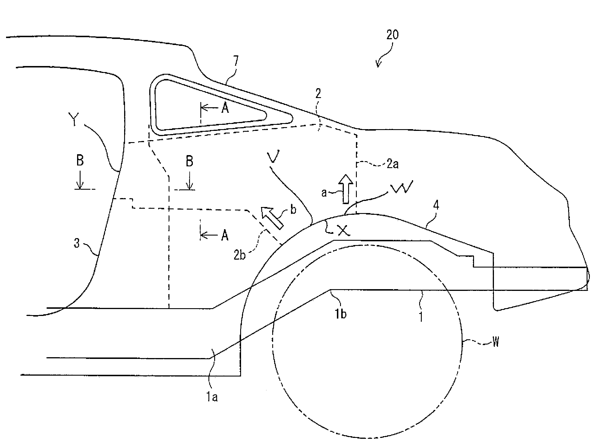
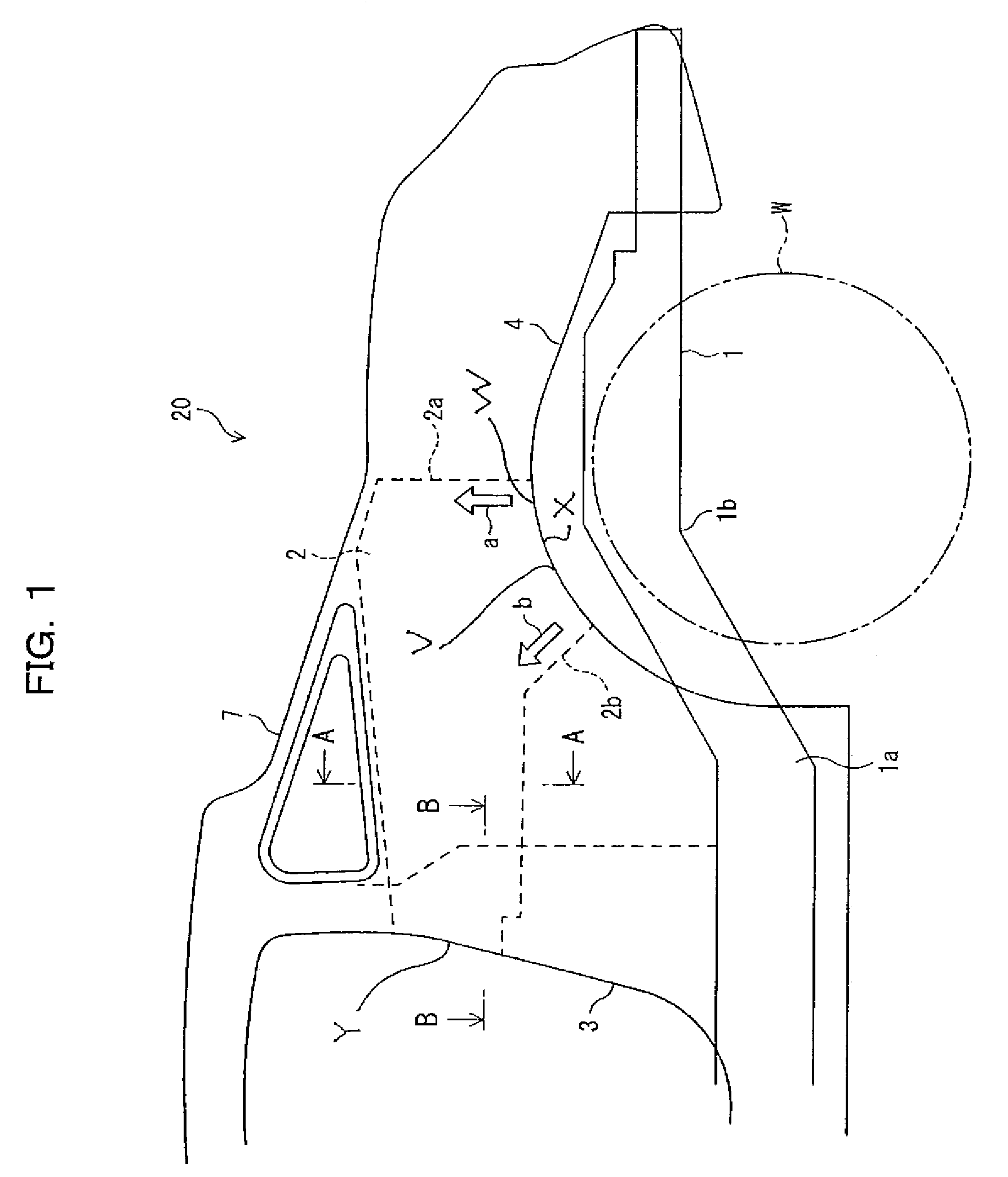
[0031]Referring to the relevant drawings, a description will be made hereinbelow of a vehicle body structure according to one preferred embodiment of the present invention. In FIG. 1, reference character 20 denotes a body structure of vehicle body (here a two-door automobile) to which the present invention is applied. The body structure 20 has a rear wheel house 4 arranged to the rear of a center pillar 3, and the rear wheel house 4 accommodates a rear wheel (rear tire) W therein.

[0032]As shown in FIG. 1, side members 1 are provided at the lower part of the vehicle body. The side members 1 extend along the longitudinal direction of the vehicle body on both sides thereof. Each side member 1 has a step-like difference in level (height) in the vicinity of a position at which a rear tire is disposed, in order to avoid interference with suspension components (not illustrated). Thus, as shown in FIG. 1, the side member 1 is bent at bend portions 1a and 1b.

[0033]Here, a cross member (not ...


PUM


Abstract

The vehicle body structure is suitable for use in two-door automobiles. The strength of a rearward part of the vehicle body is increased to reliably suppress the deformation of the vehicle body in a possible collision from behind the vehicle. The vehicle body structure includes: a rear wheel house arranged to the rear of a center pillar; and a reinforcement member directly connecting a front part in front of the top portion of the rear wheel house with the center pillar, the front part being inclusive of the top portion of the rear wheel house.

Description

BACKGROUND OF THE INVENTION[0001](1) Field of the Invention[0002]The present application relates to a vehicle body structure suitable for use in two-door automobiles.[0003](2) Description of the Related Art[0004]FIG. 11 is a schematic diagram showing a rear part of a conventional two-door vehicle body. As shown in FIG. 11, at the lower part of the vehicle body 100, side members 101 extend in the longitudinal direction of the vehicle body on both sides of the vehicle body. Each side member 101 has a step-like difference in level in the vicinity of a position at which a rear tire W is disposed, in order to avoid interference with suspension components (not illustrated). Thus, as shown in FIG. 11, the side member 101 is bent at bend portions 101a and 101b. [0005]Here, a cross member 102 extending in the widthwise direction of the vehicle body is provided at a position where a suspension of the vehicle is disposed, and this cross member extends between the side members on both sides at ...

Claims


Application Information

Patent Timeline
Patent Type & Authority Patents(United States)
IPC IPC(8): B60J7/00
CPCB62D25/02B62D25/08
Inventor YATABE, TAKAYUKIGOTO, KEISHIUMEDA, MASASHISHII, AKITOSHI
Owner MITSUBISHI MOTORS CORP
Why Eureka
Try Eureka