Laser processing apparatus

a technology of laser processing and workpiece, which is applied in the field of laser processing equipment, can solve the problems of deteriorating chip quality and damaging the device, and achieve the effect of softening the processing area of the workpi

Active Publication Date: 2009-01-06
DISCO CORP
View PDF2 Cites 123 Cited by
  • Summary
  • Abstract
  • Description
  • Claims
  • Application Information

AI Technical Summary

Benefits of technology

[0005]It is an object of the present invention to provide a laser processing apparatus which can form laser processed grooves along streets even in a wafer coated with an insulating film on the face thereof, without peeling off the insulating film.
[0010]According to the laser processing apparatus of the present invention, the first pulsed laser beam having a wavelength in the intermediate-infrared radiation region is thrown from the first laser beam irradiation means to heat and soften the processing area of the workpiece. The softened processing area is irradiated with the second pulsed laser beam having a wavelength in the ultraviolet radiation region by the second laser beam irradiation means. Thus, when the second pulsed laser beam is thrown to form a laser processed groove in the workpiece, the processing area is softened. Hence, even if an insulating film or the like is coated on the face of the workpiece., the insulating film or the like is not peeled off upon exposure to the second pulsed laser beam.

Problems solved by technology

However, the wafer having an insulating film, such as a film of silicon oxide (SiO2), coated on the surface of each device, faces the problems that irradiation with the laser beam peels off the insulating film to damage the device or deteriorate the quality of chips.

Method used


Image

  • Laser processing apparatus
  • Laser processing apparatus
  • Laser processing apparatus

Examples


Embodiment Construction

[0021]Preferred embodiments of a laser processing apparatus constituted in accordance with the present invention will now be described in detail by reference to the accompanying drawings.

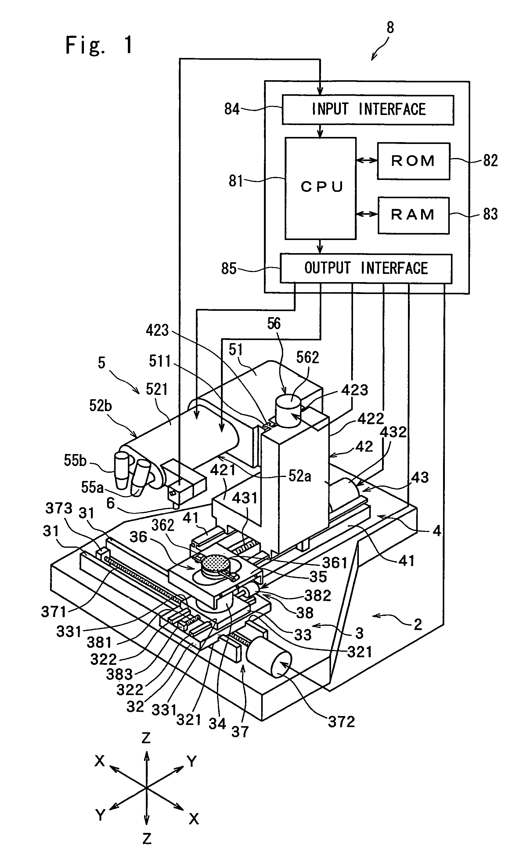
[0022]FIG. 1 shows a perspective view of the laser processing apparatus constituted in accordance with the present invention. The laser processing apparatus shown in FIG. 1 is equipped with a stationary pedestal 2, a chuck table mechanism 3, disposed on the stationary pedestal to be movable in a processing feed direction indicated by an arrow X, for holding a workpiece, a laser beam irradiation unit support mechanism 4 disposed on the stationary pedestal 2 to be movable in an indexing feed direction indicated by an arrow Y which is perpendicular to the direction indicated by the arrow X, and a laser beam irradiation unit 5 disposed on the laser beam irradiation unit support mechanism 4 to be movable in a direction indicated by an arrow Z.

[0023]The chuck table mechanism 3 is furnished with a pair of ...


PUM

PropertyMeasurementUnit
wavelengthaaaaaaaaaa

Abstract

A laser processing apparatus comprising a chuck table, laser beam irradiation means for irradiating a workpiece held on the chuck table with a laser beam, and processing feed means for processing-feeding the chuck table and the laser beam irradiation means relative to each other. The laser beam irradiation means includes first laser beam irradiation means for throwing a first pulsed laser beam having a wavelength in the intermediate-infrared radiation region, and second laser beam irradiation means for throwing a second pulsed laser beam having a wavelength in the ultraviolet radiation region. The first laser beam irradiation means and the second laser beam irradiation means are set such that at least a part, in the processing feed direction, of the focus spot of the second pulsed laser beam overlaps the focus spot of the first pulsed laser beam.

Description

FIELD OF THE INVENTION[0001]This invention relates to a laser processing apparatus for performing laser processing along streets formed in a wafer such as a semiconductor wafer.DESCRIPTION OF THE PRIOR ART[0002]In a semiconductor device manufacturing process, a plurality of regions are defined by division-scheduled lines, called streets, arranged in a lattice pattern on the face of a nearly disk-shaped semiconductor wafer, and devices, such as IC and LSI, are formed in these defined regions. The semiconductor wafer is cut along the streets to separate the regions, where the devices have been formed, thereby producing individual semiconductor chips. An optical device wafer, which has light receiving elements such as photodiodes, or light emitting elements such as laser diodes, laminated on the surface of a sapphire substrate, is also cut along streets, whereby the optical device wafer is divided into individual optical devices such as photodiodes or laser diodes for wide use as elect...

Claims


Application Information

Patent Timeline
Patent Type & Authority Patents(United States)
IPC IPC(8): B23K26/08B23K15/08B23K26/40H01L21/00
CPCB23K26/0613B23K26/083B23K26/367B23K26/409B23K2201/40B23K26/364B23K26/40B23K2101/40B23K2103/172
Inventor MORISHIGE, YUKIOMORIKAZU, HIROSHITSUCHIYA, TOSHIOTAKEYAMA, KOICHI
Owner DISCO CORP
Why Eureka
Try Eureka