Electronic control unit and electric pump

a technology of electric pump and control unit, which is applied in the direction of piston pump, magnetic circuit rotating parts, magnetic circuit shape/form/construction, etc., can solve the problems of difficult to remove bubbles from potting material in a short period of time, relatively small electronic components need to be mounted on the board,

Inactive Publication Date: 2009-01-06
AISAN IND CO LTD
View PDF21 Cites 50 Cited by
  • Summary
  • Abstract
  • Description
  • Claims
  • Application Information

AI Technical Summary

Benefits of technology

[0007]In some cases, however, relatively small electronic components need to be mounted on the board. It is easy for bubbles to become trapped in the periphery of small electronic components when the potting material is poured, and large numbers of air bubbles can get mixed in with the potting material. Furthermore, the opening for discharging air from the case is formed on one face of the case opposite one of the faces of the board. Consequently, any bubbles trapped in the potting material on the side of the board away from the opening must travel round the board before escaping through the opening. These factors made it difficult to remove bubbles from the potting material in a short period of time.
[0008]Accordingly, it is one object of the present teachings to provide an electronic control unit, in which a case accommodating a board is filled with potting material, that makes it possible to remove bubbles from the potting material in a short period of time.
[0009]In one aspect of the present teachings, an electronic control unit may comprise a case, a board disposed within the case, and electronic components mounted on the board. The case may have an opening in one face thereof opposite one of the faces of the board. The case may be filled with potting material, and the board and the electronic components may be embedded in the potting material. The distance between the electrodes of the respective electronic components mounted on the non-opening side face of the board may be greater than that of any of the components mounted on the opening-side face of the board. In other words, electronic components having a large distance between electrodes may be mounted on the non-opening side face of the board, and electronic components with a smaller distance between electrodes may be mounted on the opening-side face of the board. This structure ensures that ‘large electronic components’ that do not trap bubbles easily are mounted on the ‘non-opening side’ from which it is more difficult for bubbles to escape, while ‘small electronic components’ more likely to trap bubbles are mounted on the ‘opening side’ from which bubbles can escape more easily. Because of this, fewer bubbles are trapped on the ‘non-opening side’ from which air bubbles do not escape easily, allowing bubbles to be removed from the potting material in a shorter period of time.
[0010]Preferably, the distance between the electrodes of the electronic components mounted on the non-opening side face of the board may be greater than or equal to 2.0 mm. This allows bubbles to be removed from the potting material in a short period of time, and reduces the occurrence of shorting between the electrodes and other faults in the electronic components.
[0011]Optionally, the board may have a penetrating hole that passes through from the opening-side face to the non-opening side face of the board. This allows bubbles trapped in the potting material on the non-opening side face to pass through the penetrating hole and escape to the opening-side face of the board.
[0012]Further, a space may also be formed between the inner face of the case and the board. This allows any bubbles in the potting material on the non-opening side to escape through the space between the board and the inner face of the case to the side with the opening.

Problems solved by technology

In some cases, however, relatively small electronic components need to be mounted on the board.
These factors made it difficult to remove bubbles from the potting material in a short period of time.

Method used


Image

  • Electronic control unit and electric pump
  • Electronic control unit and electric pump
  • Electronic control unit and electric pump

Examples


Embodiment Construction

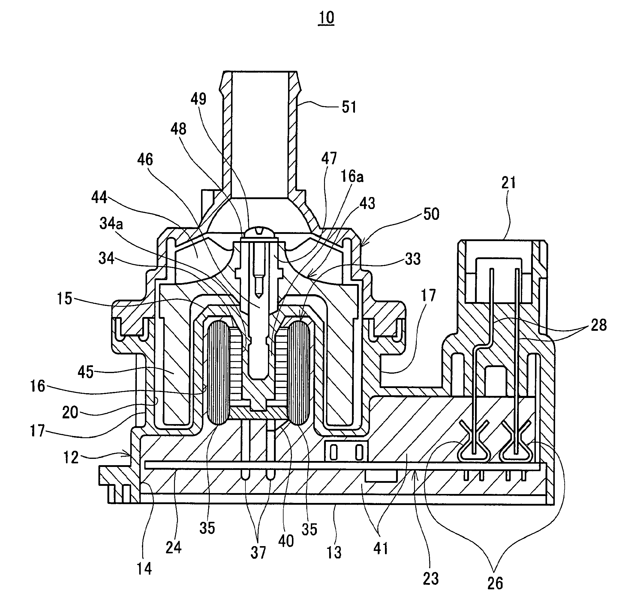
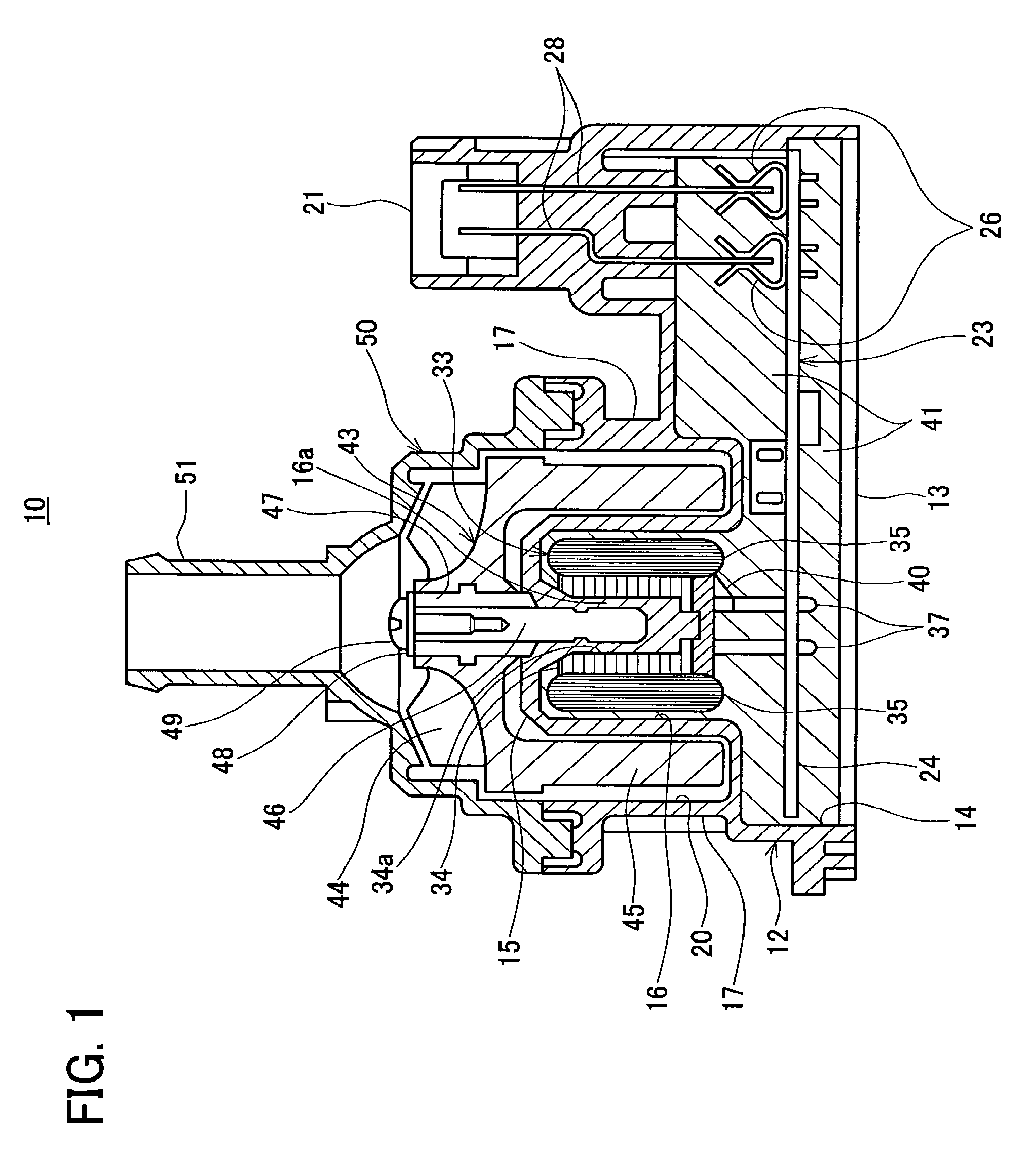
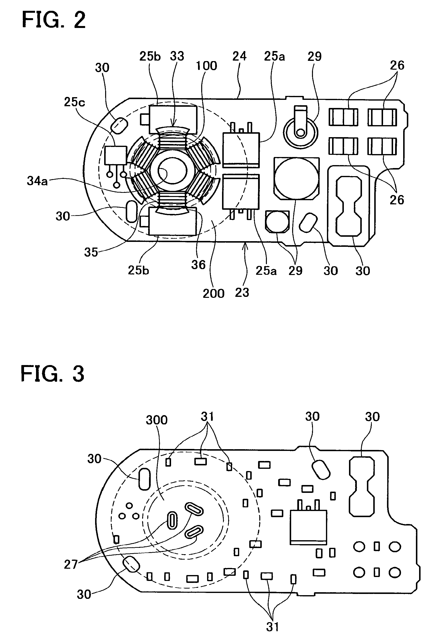
[0021]In one embodiment of the present teachings, an electric pump may comprise an electronic control unit, a stator coil controlled by the electronic control unit, and a rotor driven by the stator coil. The electronic control unit may comprise a first case, a board disposed within the first case, and electronic components mounted on the board. The stator coil may be accommodated inside the first case and electrically connected to the board. A second case may be provided adjacent to the first case, and the pump chamber may be formed by the first and second cases. The rotor may be rotatably disposed within the pump chamber. The rotor may be disposed on the inside or the outside of the stator coil. When current flows from the electronic control unit to power the stator coil, the rotor is rotated by means of a magnetic force produced by the stator coil. An impeller may be provided on the rotor. When the rotor rotates, fluid (such as fuel or water) is sucked into the pump chamber, press...


PUM


Abstract

An electronic control unit 10 may comprise a case 12, a board 23 accommodated inside the case 12, and electronic components (25, 29, 31) mounted on the board 23. An opening 13 may be formed on one face of the case 12 opposite one of the faces of the board 23. The case 12 may be filled with potting material 41, and the board 23 and the electronic components (25, 29, 31) may be embedded in the potting material 41. The distance between the electrodes of the respective electronic components (25, 29) mounted on the non-opening side face of the board 23 may be greater than that of any of the electronic components 31 mounted on the opening-side face of the board 23.

Description

CROSS REFERENCE[0001]This application claims priority to Japanese patent application number 2004-268744, filed Sep. 15, 2004, and Japanese patent application number 2004-269231, filed Sep. 16, 2004, each of which are incorporated herein by reference as if fully set forth herein.BACKGROUND OF THE INVENTION[0002]1. Field of the Invention[0003]The present invention relates to an electronic control unit for use in an electrically powered appliance (such as an electric pump, for example), and more particularly to an electronic control unit having a board on which electronic components are mounted.[0004]2. Description of the Related Art[0005]Japanese Laid-open Patent Publication No. 6-260777 discloses an electronic control unit for controlling an electrically powered appliance. This electronic control unit comprises a board mounted with electronic components and a case that accommodates the board. The case is filled with potting material, and the board and the electronic components are em...

Claims


Application Information

Patent Timeline
Patent Type & Authority Patents(United States)
IPC IPC(8): H02K11/00
CPCH05K3/284F04D13/064F04D13/0686H05K1/18H05K2203/1572
Inventor NAKANISHI, SHINGO
Owner AISAN IND CO LTD
Why Eureka
Try Eureka