
Battery charger with backup charging circuit

a secondary battery and charging circuit technology, applied in electric power, electric vehicles, transportation and packaging, etc., can solve the problems of causing damage to the secondary battery, meaningless waste of power and noise, and unstable operation of the dc/dc converter, etc., and achieve the effect of safe charging the secondary battery

Inactive Publication Date: 2009-01-06
COLLABO INNOVATIONS INC
View PDF3 Cites 26 Cited by
  • Summary
  • Abstract
  • Description
  • Claims
  • Application Information

AI Technical Summary

Benefits of technology

[0015]It is therefore an object of the present invention to provide a charger capable of safely charging a secondary battery without causing damage to the secondary battery even when the current limit value of the external power supply is less than the maximum charging current of the charger or when the battery voltage is low.

Problems solved by technology

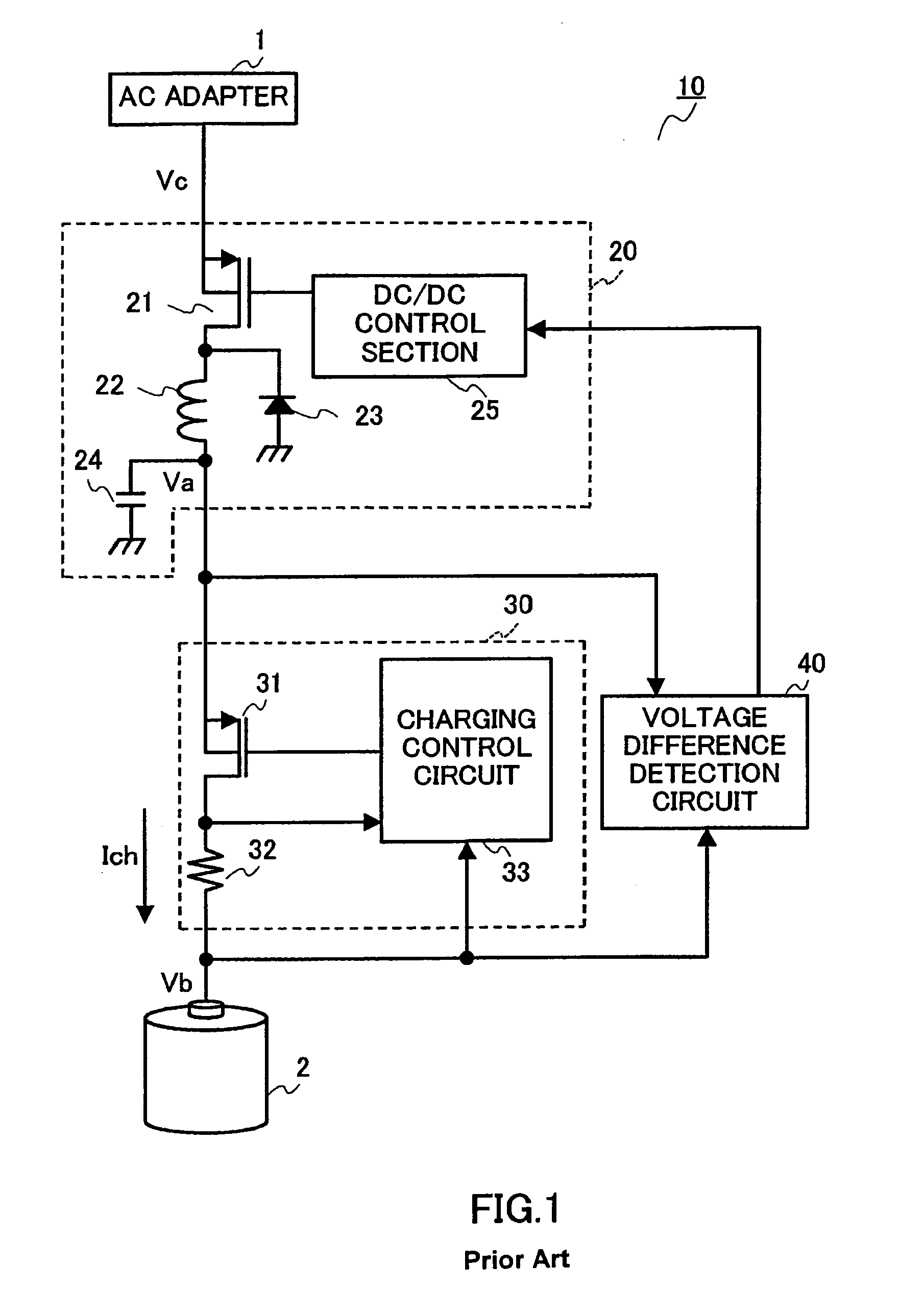
However, in such a charger of prior art, there is a problem that the operation of the DC / DC converter becomes unstable when the current limit value of the external power supply is less than the maximum charging current of the charger or when the battery voltage is low.
That is, although the operation is not performed as difference voltage output operation of DC / DC converter 20, power is supplied to DC / DC converter 20, and therefore the operation results in a meaningless waste of power and the amplification of noise.
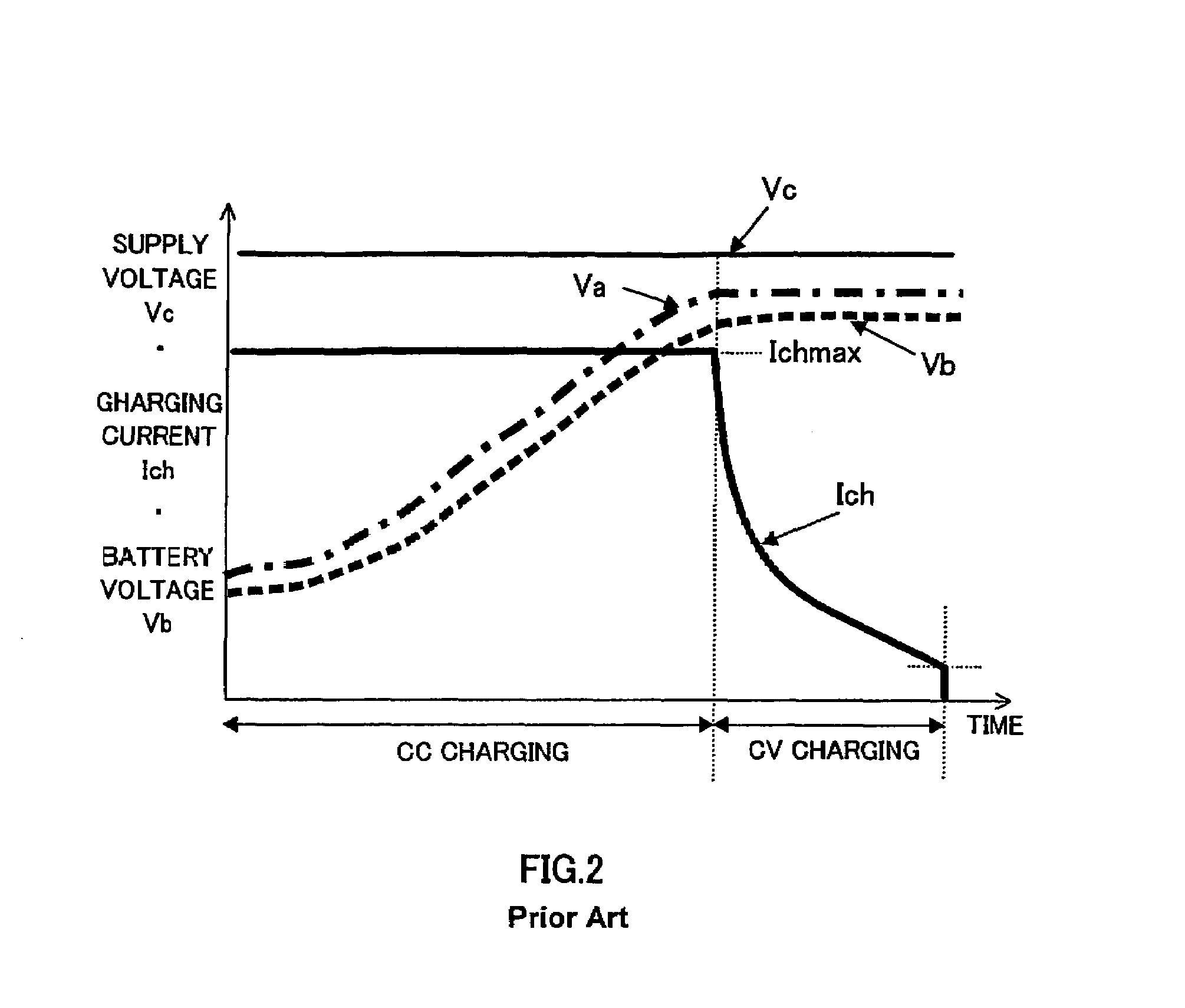
In addition, there is a risk of causing damage to secondary battery 2 if quick charging is performed at the maximum charging current when the battery voltage is low.
For example, in the initial charging start stage indicated by CC charging in FIG. 2, if the chargeable charging current is supplied to secondary battery 2 to the fullest, secondary battery 2 is damaged, resulting in deterioration, and further, causing the risk of heat generation.

Method used


Image

  • Battery charger with backup charging circuit
  • Battery charger with backup charging circuit
  • Battery charger with backup charging circuit

Examples


embodiment 1

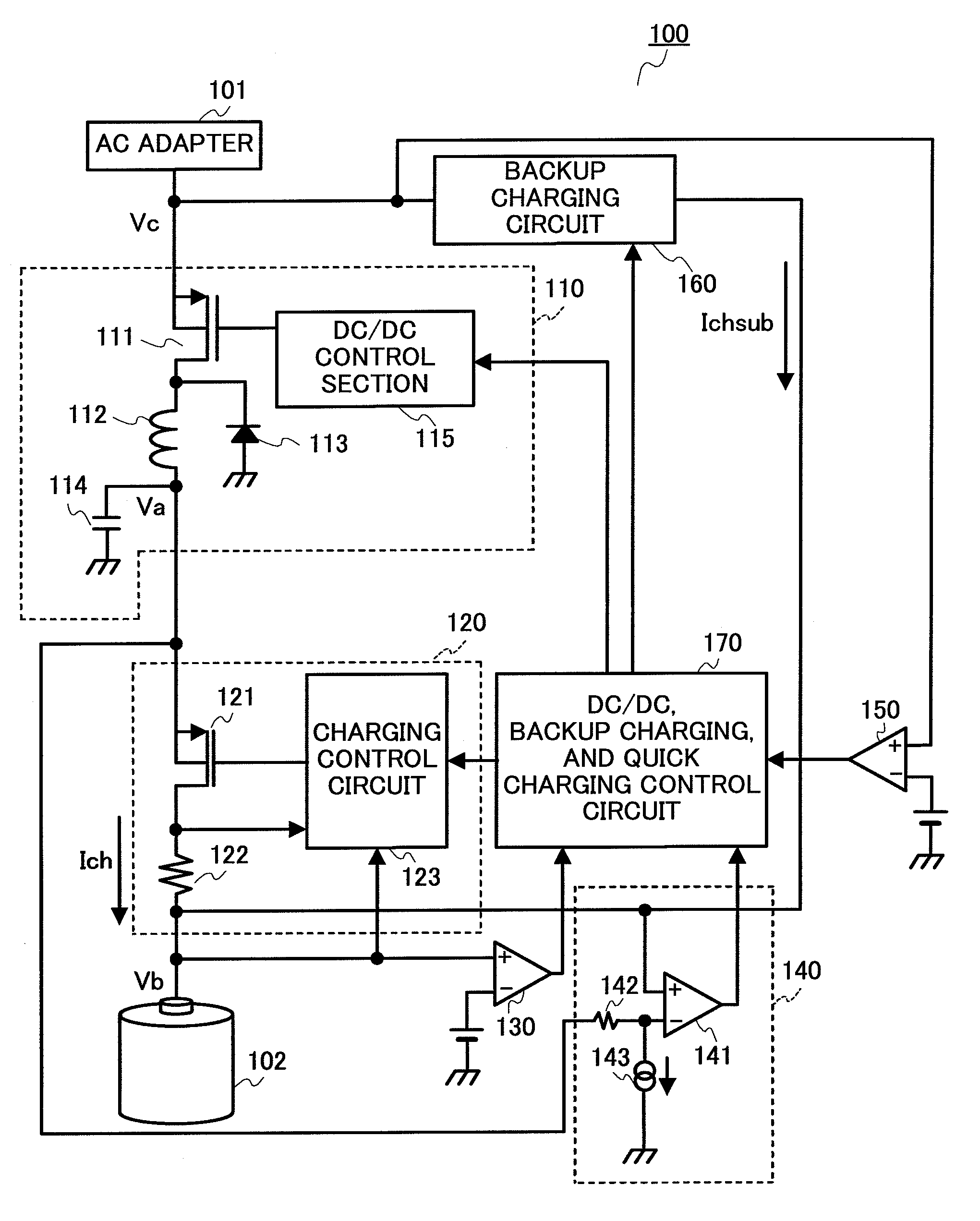
[0027]FIG. 3 is a block diagram showing the configuration of the charger according to Embodiment 1 of the present invention. This embodiment is an example of application to a charger of a mobile apparatus.

[0028]In FIG. 3, 101 is an AC adapter that supplies DC voltage Vc, 102 is a secondary battery, and 101 is a charger. Charger 100 has: step-down type DC / DC converter 110 that converts at high efficiency supply voltage Vc to voltage Va; charging control section 120 that performs control of supplying charging current Ich to secondary battery 102 based on voltage Va from DC / DC converter 110; comparator 130 that compares battery voltage Vb of secondary battery 102 with a reference voltage; voltage difference detection circuit 140 that detects the difference voltage between output voltage Va of DC / DC converter 110 and battery voltage Vb; comparator 150 that compares DC voltage Vc of AC adapter 101 with the reference voltage; backup charging circuit 160 that performs charging using a curr...

embodiment 2

[0056]Embodiment 2 is an example where charging is switched to CC charging which performs quick charging using maximum charging current Ichmax immediately after backup charging by backup charging circuit 160. The hardware configuration of the charger according to Embodiment 2 of the present invention is the same as that of charger 100 of FIG. 3 and FIG. 4, and a description thereof is omitted.

[0057]First, the charging control operation for the case where current limit value Icmax of external power supply 101 is greater than or equal to maximum charging current Ichmax of charging control section 120 will be described.

[0058]FIG. 7 is an operation waveform diagram of each section of charger 100. FIG. 7 shows the sectional time charts from the initial charging stage to charge completion of secondary battery 102 when current limit value Icmax of external power supply 101 is greater than or equal to maximum charging current Ichmax of charging control section 120. FIG. 7 shows supply volta...


PUM


Abstract

A charger capable of safely charging an apparatus even when the current limit value of an external power supply is less than the maximum charging current of the charger or when the battery voltage is low. Charger 100 has backup charging circuit 160 that performs charging using a current that is less than the charging current of charging control section 120. Control circuit 170 performs control so that charging control circuit 123 of charging control section 120 fixes charging control transistor 121 to OFF, makes backup charging circuit 160 operate, and performs backup charging using minute current Ichsub when battery voltage Vb is lower than predetermined value Vbx1, and fixes control transistor 111 of DC / DC converter 110 to ON when supply voltage Vc is less than a first supply voltage value.

Description

BACKGROUND OF THE INVENTION[0001]1. Field of the Invention[0002]The present invention relates to a charger of a secondary battery, and more particularly to a charger that efficiently charges a secondary battery such as a mobile apparatus.[0003]2. Description of Related Art[0004]In recent years, with the development of high capacity batteries used in mobile apparatuses and the development of safety designs of the mobile apparatuses during use and charging, techniques for safely and efficiently charging secondary batteries are required. The mobile apparatus charging system typically employs a configuration of using an external power supply typified by an AC adapter as the input source, and charging the secondary battery via a charger having a series regulator configuration. The series regulator is provided with a control transistor between the input and output, and controls output voltage (the charging voltage of the secondary battery) and output current (the charging current of the s...

Claims


Application Information

Patent Timeline
Patent Type & Authority Patents(United States)
IPC IPC(8): H02J7/00H02J7/04H02J7/06
CPCH02J7/022H02J7/045H02J7/02H02J2207/20H02J7/04H02J7/007182
Inventor HASHIMOTO, YUICHIRO
Owner COLLABO INNOVATIONS INC
Learn More