Gas plasma antenna

a plasma display panel and plasma technology, applied in the direction of antennas, antenna details, antenna feed intermediates, etc., can solve the problem that the antenna cannot perform electronic scanning functions, and achieve the effect of efficient reflection of incident radiation

Inactive Publication Date: 2009-01-06
IMAGING SYST TECH
View PDF78 Cites 36 Cited by
  • Summary
  • Abstract
  • Description
  • Claims
  • Application Information

AI Technical Summary

Problems solved by technology

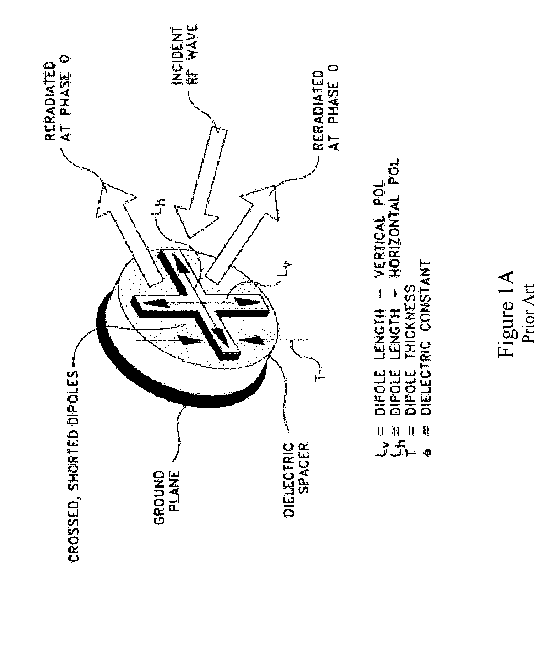
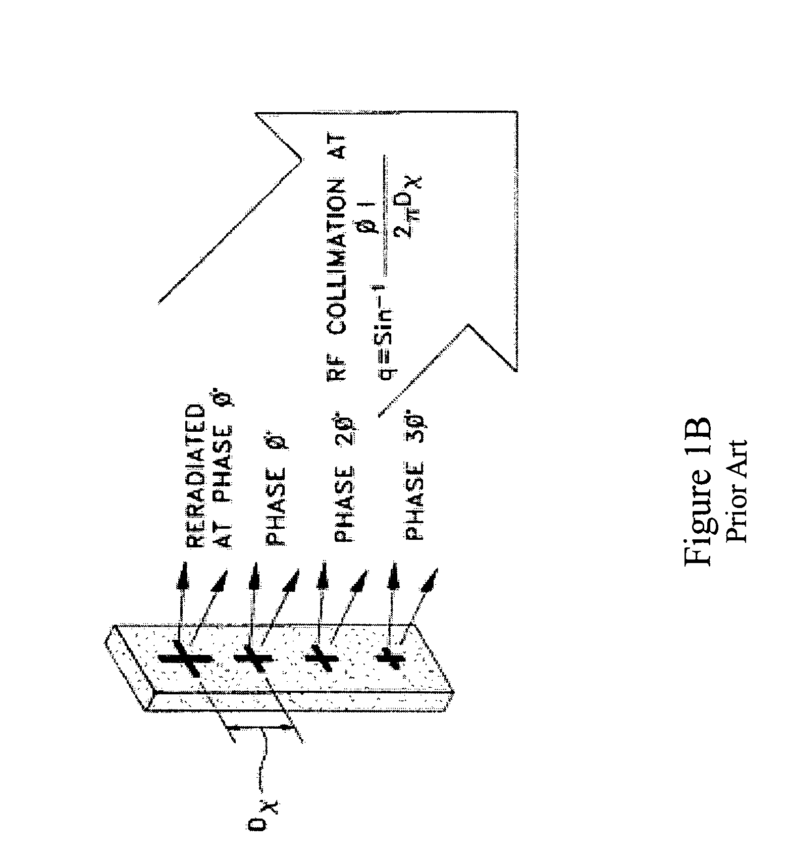
Due to the lack of dynamic reconfigurability of the dipoles, the above-described phased array antennas are incapable of dynamically varying the phase shifts associated with the dipoles and, therefore, such antennas cannot perform electronic scanning functions.

Method used


Image

  • Gas plasma antenna
  • Gas plasma antenna
  • Gas plasma antenna

Examples


Embodiment Construction

. 3 TO 9 AND SPECIFIC EMBODIMENTS

[0151]Although a sustain voltage is sufficient to maintain the firing of the plasma, the electron density is not uniform. FIGS. 3A, 3B, and 3C show the electron density fluctuates by several orders of magnitude in several microseconds. Further, the electron energy also decays very rapidly within 100 ns. This fluctuation will not allow accurate dynamic control of the antenna.

[0152]FIG. 3C is a discharge electron density graph-timing diagram showing the timing relationships of a typical plasma display panel. Each plasma display pixel acts as a capacitor producing a brief intense discharge (with an electron density of 1014 cm3 nominally on the order of 200 nanoseconds (t2) with every sustain cycle. PDP sustain cycles occur nominally and are produced every 6000 nanoseconds; meaning that while the discharge appears to be continuous (i.e., the phosphor may decay over the sustain cycle time); the electron density that effects the RF phase delay (through ref...


PUM


Abstract

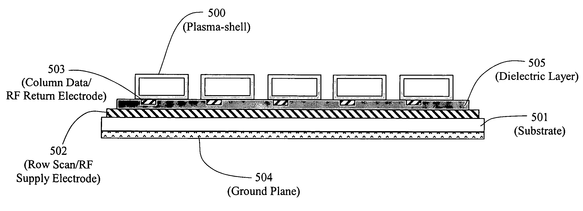
A gas plasma antenna with a rigid, flexible, or semi-flexible substrate and an improved method of generating a uniform electron density. The antenna comprises a plasma display panel (PDP) containing a multiplicity of Plasma-shells, each Plasma-shell containing a gas which is ionized to produce electron density. Each Plasma-shell acts alone or in concert with other Plasma-shells to form a dipole or pattern of dipoles.

Description

RELATED APPLICATIONS[0001]Priority is claimed under 35 USC 119(e) for Provisional Application Ser. No. 60 / 675,084, filed Apr. 27, 2005.INTRODUCTION[0002]This invention relates to phased array antennas, including dynamic gas plasma driven phased array antennas. This invention particularly relates to a plasma display panel (PDP) antenna constructed out of one or more Plasma-shells filled with an ionizable gas. The PDP antenna comprises one or more Plasma-shells on or within a rigid, flexible, or semi-flexible substrate with each Plasma-shell being electrically connected to at least two electrical conductors such as electrodes. Each gas filled Plasma-shell acts as a dipole alone or in concert with other gas filled Plasma-shells to form dipole patterns.[0003]As used herein, Plasma-shell includes Plasma-disc, Plasma-dome, and Plasma-sphere. Combinations of different Plasma-shells may be used. Plasma-shells may be also used in combination with Plasma-tubes.PLASMA PANEL BACKGROUNDPDP Struc...

Claims


Application Information

Patent Timeline
Patent Type & Authority Patents(United States)
IPC IPC(8): H01Q15/02H01Q19/06H01Q9/28
CPCH01Q1/366H01Q3/46H01Q9/16H01Q21/24
Inventor PAVLISCAK, THOMAS J.WEDDING, CAROL ANN
Owner IMAGING SYST TECH
Why Eureka
Try Eureka