Nanometer-precision tip-to-substrate control and pattern registration for scanning-probe lithography

a scanning probe and pattern registration technology, applied in the field of interferometricspatial phase imaging, can solve problems such as degrading the quality of scanned images

Inactive Publication Date: 2009-01-06
MASSACHUSETTS INST OF TECH
View PDF15 Cites 38 Cited by
  • Summary
  • Abstract
  • Description
  • Claims
  • Application Information

AI Technical Summary

Problems solved by technology

Tip perturbations degrade the quality of scanned images.

Method used


Image

  • Nanometer-precision tip-to-substrate control and pattern registration for scanning-probe lithography
  • Nanometer-precision tip-to-substrate control and pattern registration for scanning-probe lithography
  • Nanometer-precision tip-to-substrate control and pattern registration for scanning-probe lithography

Examples


Embodiment Construction

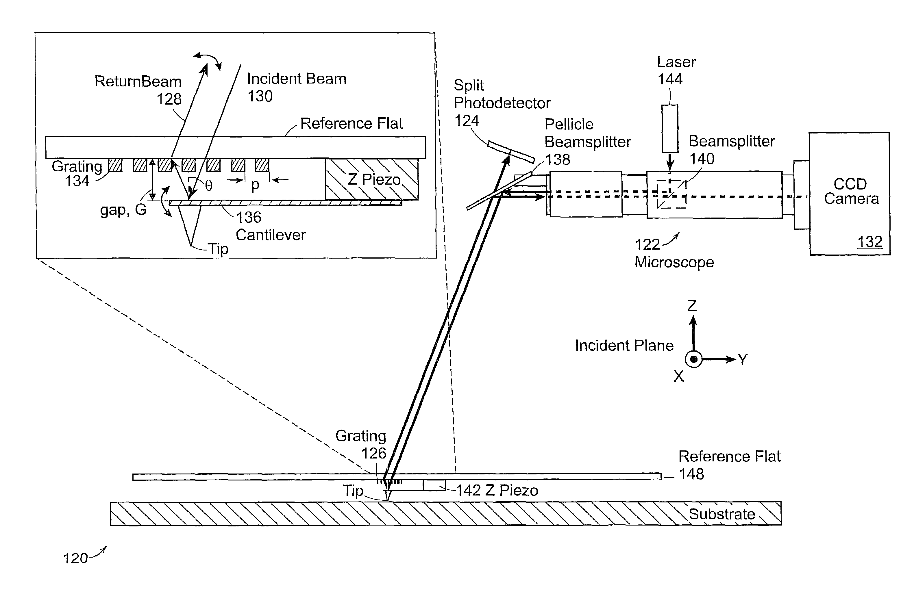
[0017]The invention relates to a technique for direct, nanometer-precision referencing of a scanning probe tip to a substrate, using Interferometric-Spatial-Phase Imaging (ISPI), which is being applied to template alignment and gap control.

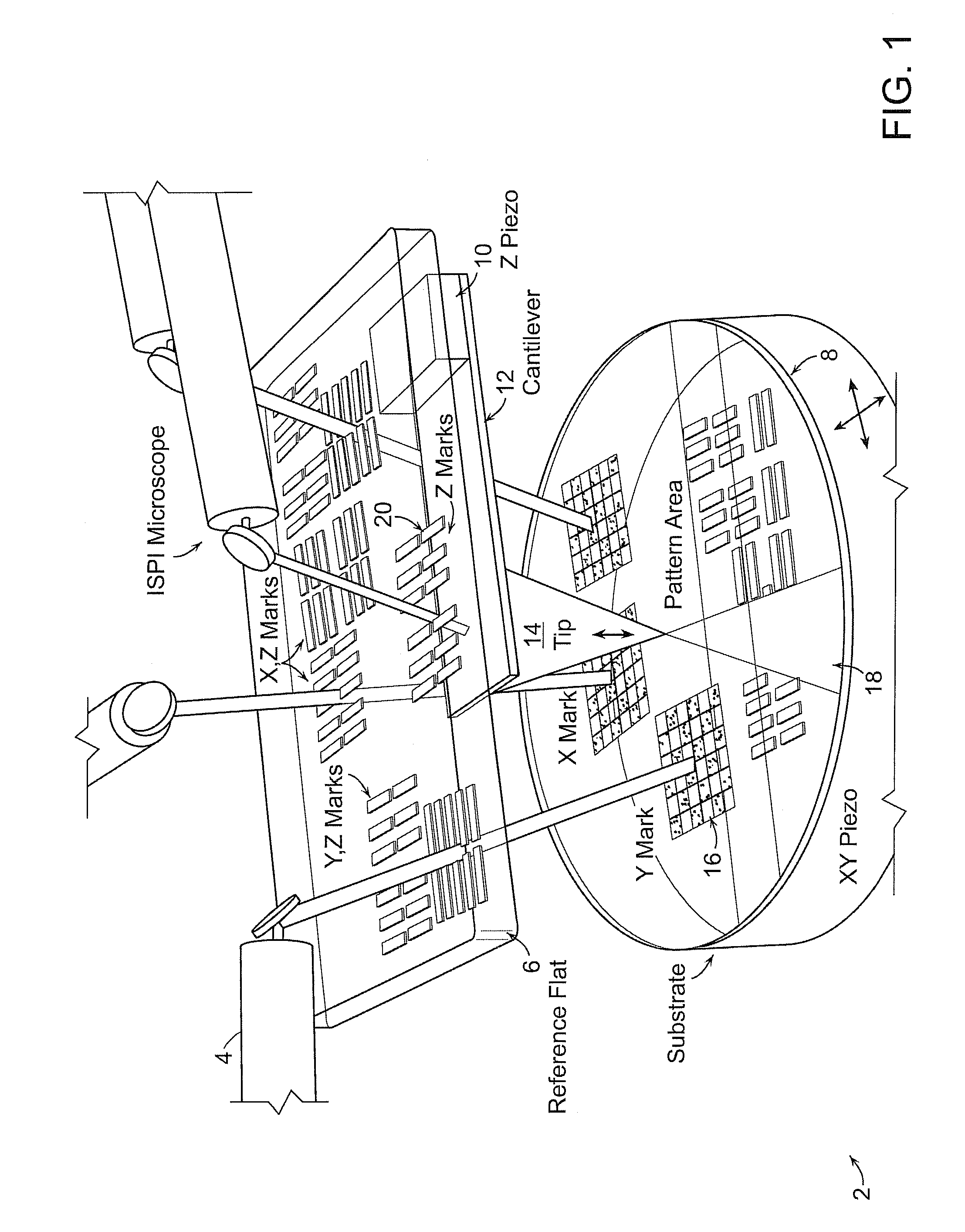
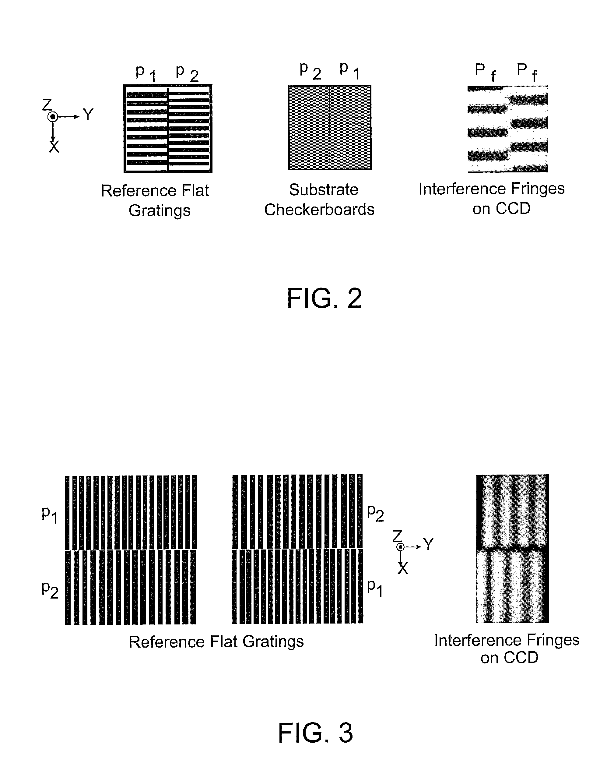
[0018]In accordance with an exemplary embodiment of the invention, a probe tip 14 is attached to a transparent, planar support structure 6, such as a fused silica plate, referred to herein as a reference flat, containing grating patterns. Checkerboard marks 16 form complementary patterns on the substrate 8, as illustrated in FIG. 1. The marks 16 are illuminated with spatially-coherent light at an oblique angle and interference patterns encoding position are detected with darkfield microscopes at a similar angle produced by ISPI microscopes 4. The measurements are used to control the lateral position of the tip 14 with respect to the substrate 8.

[0019]During lithography, the substrate 8 is scanned underneath the tip in X and Y directions, while the...


PUM


Abstract

An interferometric-spatial-phase imaging (ISPI) system includes an alignment mechanism for obtaining continuous six-axis control of a scanning probe tip with respect to a coordinate system attached to a substrate. A gap detection mechanism measures tip height above a substrate and controls tip approach toward the substrate of one or more tips, as well as measures tip deflection during surface contact of the one or more tips. A plurality of complementary marks is provided for attachment to the one or more tips. A plurality of grating marks is provided to backdiffract a reflected beam from a flexible cantilever to detect high-frequency tip deflection in a compact configuration of a light source and a light detector.

Description

PRIORITY INFORMATION[0001]This application claims priority from provisional application Ser. No. 60 / 790,910 filed Apr. 11, 2006, which is incorporated herein by reference in its entirety.BACKGROUND OF THE INVENTION[0002]The invention relates to the field of interferometric-spatial-phase imaging (ISPI), and in particular to nanometer-precision referencing of a scanning probe tip to a substrate.[0003]Since the invention of the scanning probe microscope in 1981, tip position has been subject to drift and perturbations that introduce disparities between the tip position and its intended position on a Cartesian grid. Tip perturbations degrade the quality of scanned images. Of more significance is the application to scanning probe lithography, which has been shown to write sub-5 nm features, and manipulate single molecules. Precise tip control, a priori, and contemporaneous to lithographic patterning, is essential for viable lithography at the extreme limit of molecular patterning.SUMMARY...

Claims


Application Information

Patent Timeline
Patent Type & Authority Patents(United States)
IPC IPC(8): G01B11/02G01Q20/02G01Q30/02G01Q70/04G01Q80/00
CPCB82Y10/00B82Y35/00B82Y40/00G01Q20/02G01Q30/02G01Q70/04G03F7/0002G03F9/7003G03F9/7015G03F9/7038G03F9/7042G03F9/7049G03F9/7061G03F9/7076G01Q80/00
Inventor MOON, EUCLID E.
Owner MASSACHUSETTS INST OF TECH
Why Eureka
Try Eureka