Memory synchronization method and refresh control circuit

a memory synchronization and control circuit technology, applied in the direction of digital transmission, generating/distributing signals, instruments, etc., can solve the problems of lockstep operation not being assured, system performance degradation of memory access, etc., to achieve the effect of reducing the performance degradation of normal memory access

Active Publication Date: 2009-01-06
NEC CORP
View PDF16 Cites 2 Cited by
  • Summary
  • Abstract
  • Description
  • Claims
  • Application Information

AI Technical Summary

Benefits of technology

[0029]An object of the present invention is to provide a memory synchronization method and a refresh control circuit which can synchronize timing of refresh of multiple ranks of mounted memory and minimize performance degradation of normal memory access.
[0030]According to the present invention, normal refresh is performed to the multiple ranks of mounted memory in a normal state, where the refresh is sequentially performed by using a count value of a counter initialized by a synchronous reset signal at predetermined first intervals. In the case where the synchronous reset signal becomes active, high-speed refresh is performed by sequentially performing the refresh at second intervals which are shorter than the first intervals. Thus, the synchronous reset signal is given in the same timing to a board to be synchronized. And the counter as the timing for the refresh is initialized so that the timing for the refresh thereafter synchronizes. Moreover, the refresh is intensively performed only when the synchronous reset signal is given so that the performance degradation of normal memory access is minimized.

Problems solved by technology

Although Japanese Patent Laid-Open No. 1995-73059 and Japanese Patent Publication No. 1995-9625 describe a method of hiding the refresh operation from other memory access by delaying the refresh operation, there is a problem that the lockstep operation cannot be assured in the case where the counter value for deciding the refresh timing is different by the board.
There is also a problem that performance degradation of the memory access occurs in the system which assures the lockstep by waiting for the timing for returning read data to the module having made a request to the memory.

Method used


Image

  • Memory synchronization method and refresh control circuit
  • Memory synchronization method and refresh control circuit
  • Memory synchronization method and refresh control circuit

Examples


Embodiment Construction

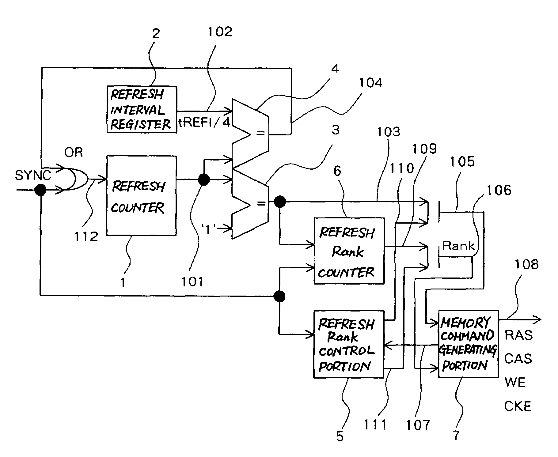
[0048]FIG. 7 is a diagram showing an embodiment of a refresh control circuit according to the present invention.

[0049]As shown in FIG. 7, this embodiment is composed of a refresh counter 1 as a first counter, a refresh interval register 2 as refresh interval setting means, a refresh interval comparison portion 4 as first comparison means, a refresh timing comparison portion 3 as second comparison means, a refresh rank counter 6 as a second counter, a refresh rank control portion 5 and a memory command generating portion 7. This embodiment synchronizes timing of refresh of multiple ranks of mounted memory.

[0050]The refresh counter 1 counts the timing for performing the refresh. The refresh counter 1 operates in synchronization with a clock signal and increases by +1 each time a clock rises so as to output a refresh count value 101. And the count value is initialized by a synchronous reset signal SYNC or a refresh initialization signal 104.

[0051]The refresh interval register 2 is a re...


PUM


Abstract

Rank numbers specified by a second counter are refreshed in sequence by using a count value of a first counter which is initialized by a synchronous reset signal and counts timing for performing refresh, and the rank numbers specified by a refresh rank control unit are continuously refreshed in sequence in the case where the synchronous reset signal is active.

Description

BACKGROUND OF THE INVENTION[0001]1. Field of the Invention[0002]The present invention relates to a memory synchronization method and a refresh control circuit for synchronizing timing for refresh of multiple ranks of mounted memory.[0003]2. Description of the Related Art[0004]There is a conventionally known fault-tolerant computer which multiplexes (double or triple for instance) components constituting hardware of the computer such as a CPU (Central Processing Unit), a memory, a disk, a network, a power supply and the like in a computer system to allow uninterrupted operation without stopping the computer system even if one of the components is at fault.[0005]In the case of the fault-tolerant computer, there are a lockstep method wherein multiplexed mutual components constantly executes the same operation in the same timing and in synchronization and a method of allowing certain components to go out of synchronization by getting processing results together and making a comparison. ...

Claims


Application Information

Patent Timeline
Patent Type & Authority Patents(United States)
IPC IPC(8): G11C7/00
CPCG06F13/1636G11C11/406G11C11/40611
Inventor TANAKA, YUKIHIRO
Owner NEC CORP
Why Eureka
Try Eureka