Method and apparatus for making a highly uniform low-stress single crystal by drawing from a melt and uses of said crystal

a single crystal, highly uniform technology, applied in the direction of single crystal growth details, crystal growth process, under a protective fluid, etc., can solve the problems of stress birefringence, unsatisfactory optical quality, and further miniaturization of structural elements, so as to reduce heat loss, reduce stress-induced birefringence, and reduce the minimum radial and/or axial temperature gradient

Inactive Publication Date: 2009-01-13
SCHOTT AG
View PDF14 Cites 9 Cited by
  • Summary
  • Abstract
  • Description
  • Claims
  • Application Information

AI Technical Summary

Benefits of technology

[0017]It is a further object of the present invention to provide a method of making the crystals according to the invention, which can be performed with a comparatively simple apparatus, which can be built from commercially obtainable parts.
[0024]In this way it is possible to draw a large crystal, especially with a planar growth front, from the melt, in which no or only slight detectable growth rings are present. Above all, the crystals made according to the invention have scarcely any fishtail pattern, since a flat planar growth front is produced in the procedure according to the invention.
[0025]The method according to the invention is preferably performed with an after-heating system. This crucible after-heating system comprises an after-heating chamber arranged over the melting chamber analogous to a pot, which receives the already prepared drawn crystal pieces. The interior surface of this after-heating system preferably is made of the same material as the crucible, which receives the melted fluid crystal mass. It is thermally insulated on its outer side in order to reduce heat losses. The after-heating chamber preferably has as high as possible a temperature during the growing of the large-diameter crystal, which produces minimum radial and / or axial temperature gradients. This temperature is greater than 1400° C., preferably greater than 1600° C., and especially preferably greater than 1800° C. This is achieved because the after-heating chamber provides as uniform planar heat transfer as possible and is the first of this type of after-heating system. In this way the crystal can directly experience an after-tempering from the above-mentioned temperature to room temperature, which leads to a further reduction of the stress-induced birefringence.
[0026]During the growth of the crystal the uniform temperature field at a high temperature level causes an additional reduction of the interfering influences on the surface temperature of the melt. This thus leads to a reduction of the temperature fluctuations in the melt at the high temperature existing there. It is also possible to control the diameter of the growing crystal by means of the temperatures existing in the after-heater, alone or in combination with other growth parameters.
[0029]The after-heating chamber formed as an after-heating system provides an additional advantage, which is that a diaphragm built in between the crucible and the after-heating chamber permits a separation of both regions and separate temperature control of both regions, but with certain limitations due to its opposing influences. However an opening must still be permitted in the diaphragm to permit measurement of the surface temperatures at measurable locations for average surface temperature fluctuations.
[0035]The purity of the starting material for the method of making the crystals according to the invention should be of the so-called 5N (i.e. 5 nine) purity, also at least 99.999% pure. Rare earth and alkali impurities are especially critical and thus should be avoided in the starting material. Starting material with a purity of 6N are even more preferably, so that 6N crystals may be obtained. Large volume, doped crystals (e.g. Nd:YAG) of improved quality and improved volume yield are obtained by means of the method according to the invention. Even in the case of making doped crystals, in which of course in contrast to undoped crystals pronounced growth strips can occur, quality advantages still can be obtained due to increased volume yields during manufacture.

Problems solved by technology

Increasing requirements for increasingly higher integration density result in further miniaturization of structural elements and require forming increasingly smaller structures in the photolithograph processing.
These dimensions are essentially too small for making lens blanks for projection objectives of a stepper and their optical quality (index of refraction uniformity, stress birefringence, DUV transmission) is completely unsatisfactory.
Up to now however this technology cannot produce crystals that meet the requirements for optical elements in lithography steppers.
Now it is known that the convection flow in the melt present in the crucible is poor, so that heating by means of a heating element arranged on or in the crucible wall produces a free or basic convection.
However these opposing flow and convection processes are unstable and especially easily changed by changing the temperature profile in the crucible or the rotation speed.
The resulting fluctuations and / or instabilities of the temperature act directly on the growth process at the phase boundaries between the crystal and melt and bring about fluctuations in the growth speed, which produce troublesome contrasting strips (growth strips or striations) in the finished crystal.
They impair the optical uniformity of the crystal.
It has now been shown that the condensation heat released by condensation at the phase boundary surface produces temperature oscillations and thus the undesirable growth strips, which are still observable in the finished crystal.
Thus a lens of this type is no longer useable for the above-described application.
Currently it is not possible to keep the behavior of the convection reproducible over the entire growth period due to the competition between natural convention and forced convection.
If forced convection dominates the convection processes, an especially undesirable concave phase boundary arises with all the negative effects of growth defects.
The current control methods for drawing speed, rotation speed, and optionally heating power depending on the crystal weight, which are practiced according to the state of the art, have not been sufficient for that purpose.
Although this method already produces improvements in the uniformity properties of the crystals, the crystals still do not have the uniformity required for optical elements.

Method used


Image

  • Method and apparatus for making a highly uniform low-stress single crystal by drawing from a melt and uses of said crystal
  • Method and apparatus for making a highly uniform low-stress single crystal by drawing from a melt and uses of said crystal
  • Method and apparatus for making a highly uniform low-stress single crystal by drawing from a melt and uses of said crystal

Examples


Embodiment Construction

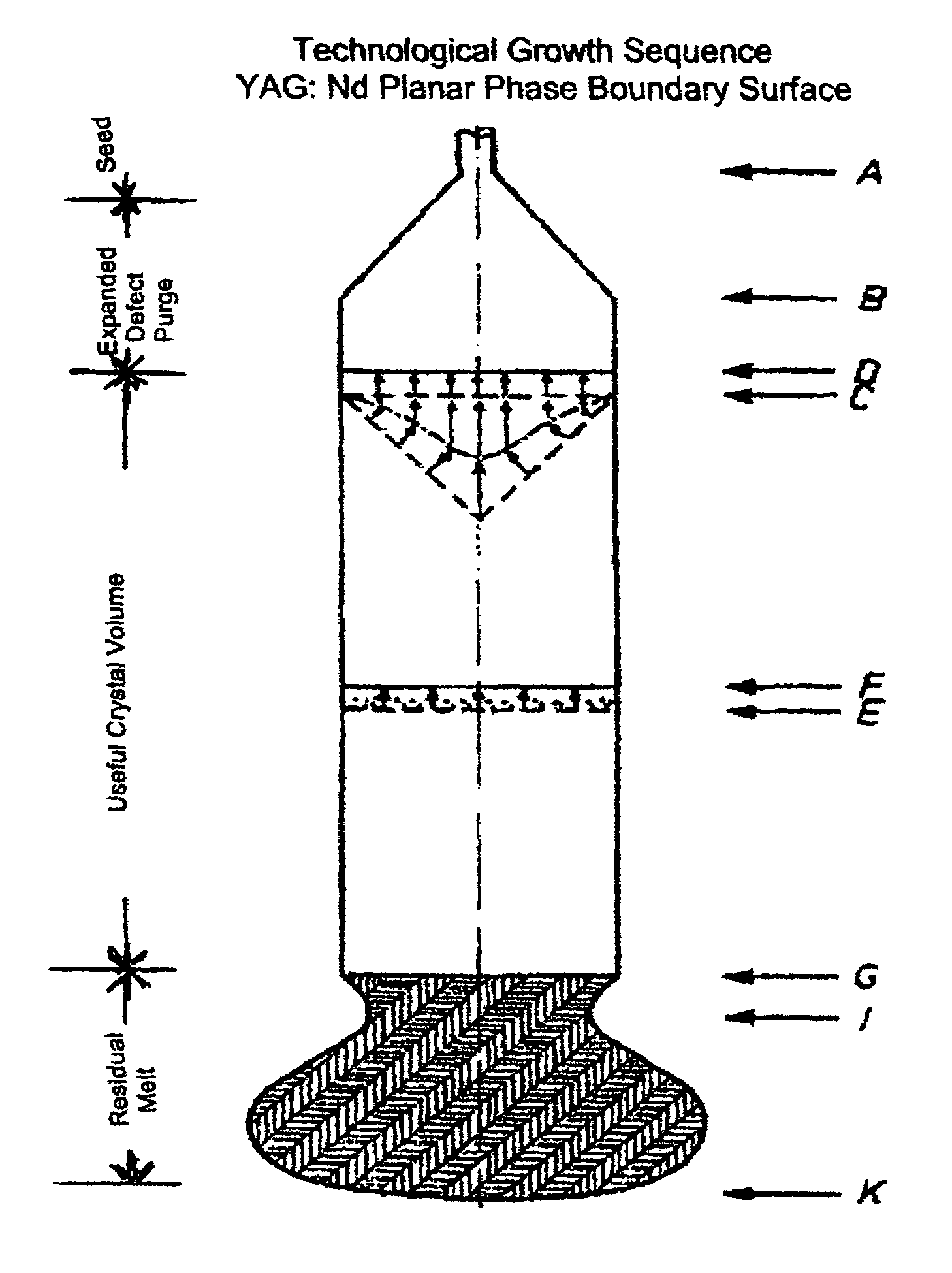
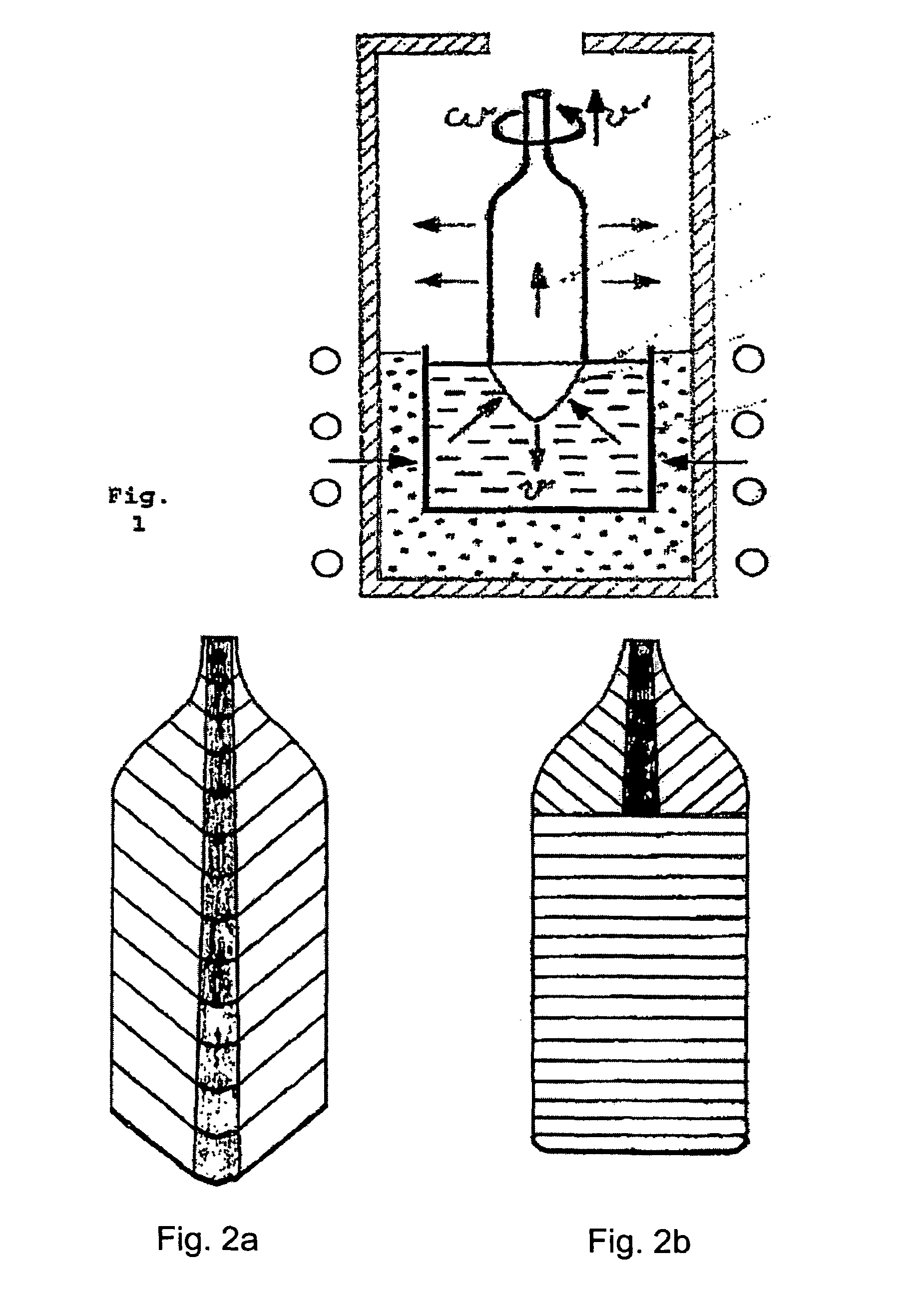
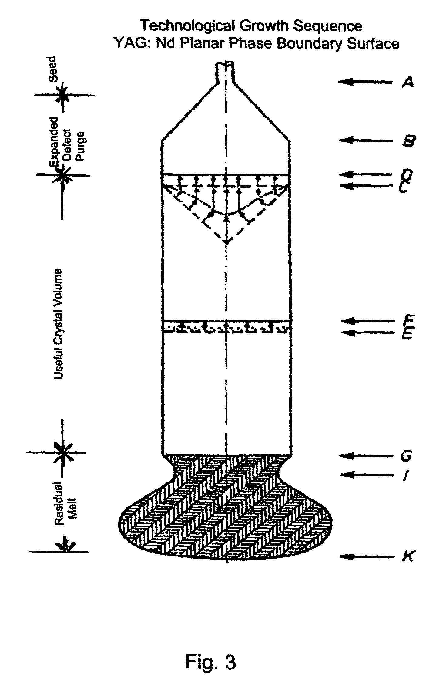
[0045]In the method according to the invention a seed crystal with a small diameter, which is oriented in the desired direction, is immersed in a melt of crystal raw material, especially a highly pure material, and is slowly drawn out of the melt in a vertical direction while it is rotated and while heat is removed from the melt. During this growing process the drawing speed of the rotating crystal seed is first set so that it increases from a small diameter (FIG. 3a at A) to a large desired diameter (FIG. 3a at B). One type of drawing with an increase of diameter can start in the method according to the invention with a convex cone-shaped growth front according to the state of the art. In this first stage it is also not necessary to take care to avoid temperature fluctuations. In this stage the growing crystal can have a fishtail pattern according to the state of the art (FIG. 2b). When the crystal has reached the desired diameter (FIG. 3 at B), it is grown further to reach a desir...


PUM

PropertyMeasurementUnit
diametersaaaaaaaaaa
melting temperaturesaaaaaaaaaa
diametersaaaaaaaaaa

Abstract

The method provides a uniform low-stress single crystal in a predetermined crystal orientation. The method of making it includes immersing a single crystal held at a temperature under its melting point in a melt of crystal raw material and drawing it from the melt to grow the crystal. The crystal and / or melt are rotated relative to each other during the crystal growth. A planar phase boundary surface is maintained by detecting at least one characteristic surface temperature in an interior of a crucible containing the melt and controlling temperature fluctuations by increasing or decreasing the rotation speed when they occur. The single crystals obtained by this method have a diameter of at least 50 mm and no visible growth strips in a fishtail pattern when a 2-mm thick sample is observed between crossed polarizers. Optical elements suitable for DUV lithography can be made from these crystals.

Description

BACKGROUND OF THE INVENTION[0001]1. The Field of the Invention[0002]The present invention relates to a method of making highly homogeneous low-stress single crystals with a predetermined orientation by immersing a single crystal in a melt and slowly drawing the single crystal out of the melt while crystallization is occurring, to an apparatus for performing the method of making the single crystals, and to the uses of the single crystals made by the method.[0003]2. Related Art[0004]The use of crystalline material for making lenses and optical elements is known. Particularly integrated circuits made by photolithography require large-volume calcium fluoride single crystals, which are permeable to short wavelength light up to a working wavelength of about 130 nm. Increasing requirements for increasingly higher integration density result in further miniaturization of structural elements and require forming increasingly smaller structures in the photolithograph processing. For these reaso...

Claims


Application Information

Patent Timeline
Patent Type & Authority Patents(United States)
IPC IPC(8): C30B15/20
CPCC30B15/14C30B29/28C30B29/22Y10T117/1004
Inventor WEHRHAN, GUNTHERPARTHIER, LUTZRYTZ, DANIELDUPRE, KLAUSACKERMANN, LOTHAR
Owner SCHOTT AG
Why Eureka
Try Eureka