Low profile antenna pair system and method

a low-profile, antenna-based technology, applied in the direction of polarised antenna unit combinations, resonant antennas, antenna earthings, etc., can solve the problems of reducing the bandwidth and efficiency of individual antenna elements, the difficulty in reducing the space occupied by the antenna system, and the inability to apply the methods and means used to miniaturize electronic circuits to miniaturize antennas

Inactive Publication Date: 2009-01-13
MOTOROLA SOLUTIONS INC
View PDF15 Cites 17 Cited by
  • Summary
  • Abstract
  • Description
  • Claims
  • Application Information

AI Technical Summary

Problems solved by technology

However, the methods and means used to miniaturize electronic circuits cannot always be applied to miniaturize antennas because antennas operate under the principles of Maxwell's equations, which, roughly speaking, stipulate that if antenna efficiency is to be preserved, the size of the antenna must be scaled according to the wavelength of the carrier frequency of the wireless signals that are to be received and / or transmitted.
Compounding the challenge of reducing antennas size is that for many wireless communication devices, the antenna system needs to support operation at multiple frequencies, for instance, in multiple relatively wide frequency bands.
However, using separate antennas to support separate operating frequencies has also led to difficulty in reducing the space occupied by the antenna system.
Unfortunately, these systems have not been able to be successfully miniaturized, for at least the reason that individual antenna element bandwidth and efficiency are reduced upon miniaturization and, furthermore, elements forming a system have not been able to be properly isolated, thereby degrading system performance.

Method used


Image

  • Low profile antenna pair system and method
  • Low profile antenna pair system and method
  • Low profile antenna pair system and method

Examples


Embodiment Construction

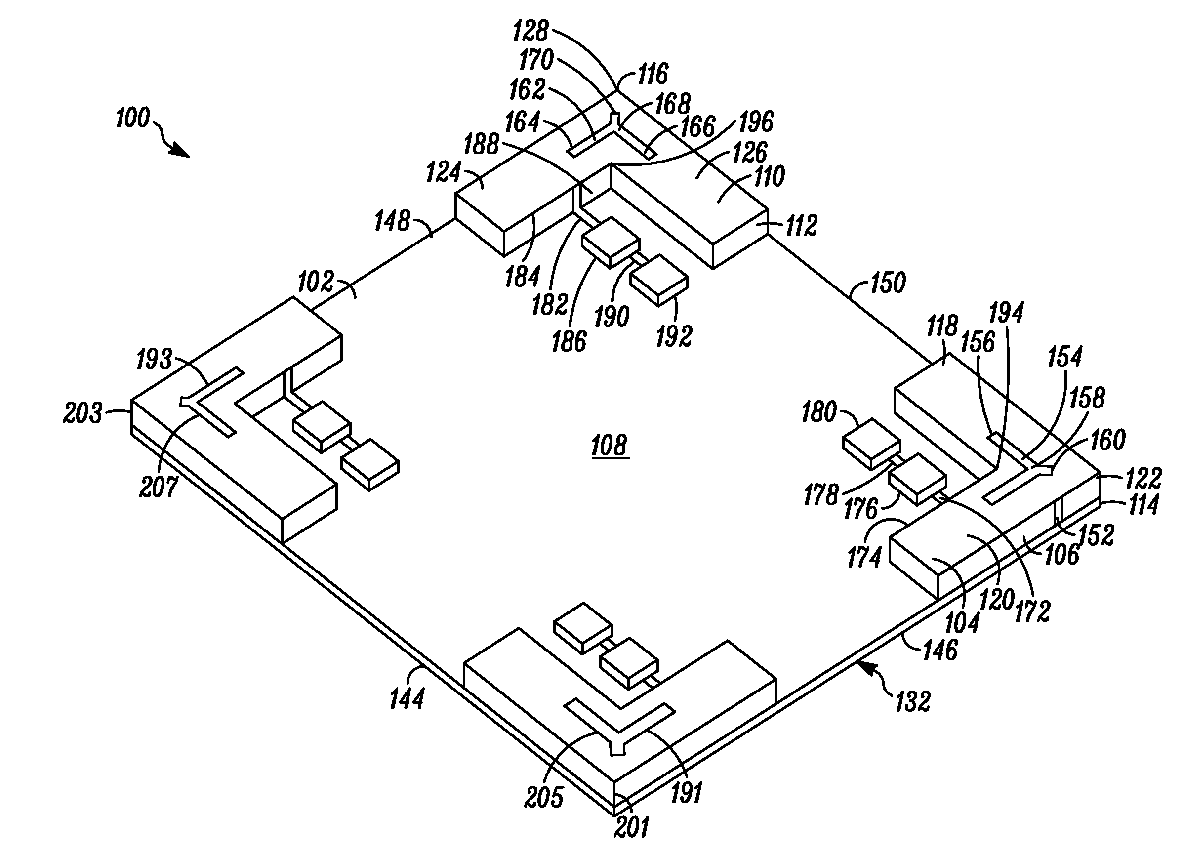
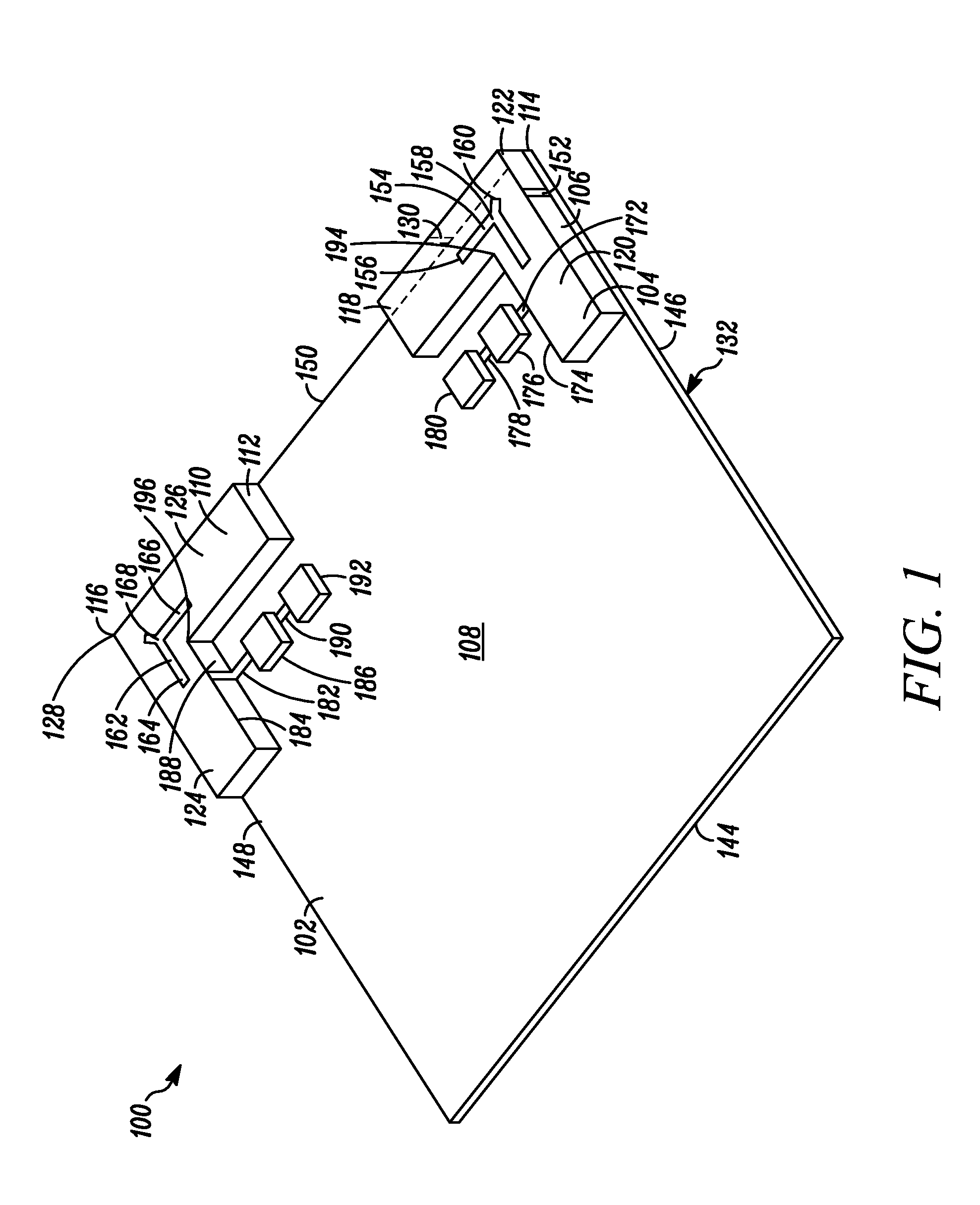
[0016]Generally speaking, pursuant to the various embodiments, antenna systems are provided that are small in size, low in profile, and are operated at multiple frequencies. These approaches also allow for the transmission and reception of circularly polarized radiation and have antenna elements that are effectively isolated from each other. Those skilled in the art will realize that the above recognized advantages and other advantages described herein are merely illustrative and are not meant to be a complete rendering of all of the advantages of the various embodiments.

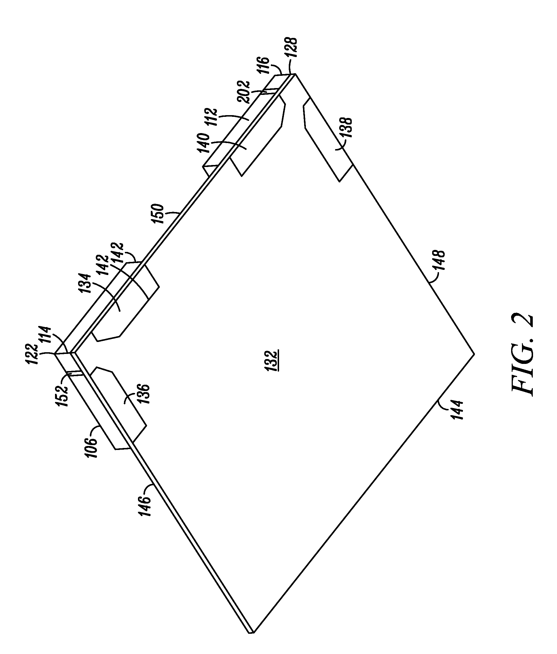
[0017]In some of these embodiments, an antenna system includes a ground plane having a first corner and a second corner. The first corner is in spaced relation to the second corner, and the first corner and the second corner are positioned along a first common edge of the ground plane. In one example, the first common edge is less than one third wavelength in length (or less) with respect to a frequency of interest....


PUM


Abstract

An antenna system includes a ground plane including a first corner and a second corner that are positioned along a first common edge. A first antenna element is disposed at the first corner of the ground plane and includes a first slot. A second antenna element is disposed at the second corner of the ground plane and includes a second slot. The first antenna element and the second antenna element are fed with an electromagnetic signal and the electromagnetic signal at the first antenna element is approximately 90 degrees shifted from the signal at the second antenna element. The first antenna element and the second antenna element form an antenna structure, and the antenna structure transmits circularly polarized radiation.

Description

TECHNICAL FIELD[0001]The technical field relates generally to wireless communication devices and more particularly to antennas for wireless communication devices.BACKGROUND[0002]The deployment of cellular networks, satellite networks and other wireless networks has greatly expanded the use of mobile wireless communication devices. Whether a wireless communication device is a handheld device or a vehicle mounted device, there is an interest in making the devices small so that they can be conveniently carried or accommodated in small spaces.[0003]Advances, by many orders of magnitude, in the degree of integration and miniaturization of electronics over the past few decades have facilitated extreme miniaturization of transceiver electronic circuits. However, the methods and means used to miniaturize electronic circuits cannot always be applied to miniaturize antennas because antennas operate under the principles of Maxwell's equations, which, roughly speaking, stipulate that if antenna...

Claims


Application Information

Patent Timeline
Patent Type & Authority Patents(United States)
IPC IPC(8): H01Q1/38H01Q5/00H01Q5/40
CPCH01Q5/00H01Q9/0421H01Q5/40H01Q21/24H01Q9/0442
Inventor BIT-BABIK, GIORGIDI NALLO, CARLOSVIGELJ, JOHN A.
Owner MOTOROLA SOLUTIONS INC
Why Eureka
Try Eureka