Cable simulation device and method

a simulation device and cable technology, applied in the direction of instrumentation, program control, line-transmission details, etc., can solve the problems of limiting the simulation of only differential mode attenuation in the simulation of cable devices, and not always feasible to connect two communication devices together using actual transmission lines at actual lengths for testing purposes

Active Publication Date: 2009-01-13
ADTRAN
View PDF7 Cites 12 Cited by
  • Summary
  • Abstract
  • Description
  • Claims
  • Application Information

AI Technical Summary

Problems solved by technology

Communication devices, e.g., transmitters or receivers, are often designed and tested in a laboratory environment, and connecting two communication devices together using actual transmission lines at actual lengths for testing purposes is not always feasible.
However, limiting simulation of only differential mode attenuation in cable simulators sometimes poses a problem when the differential component attenuation reaches a critical level.

Method used


Image

  • Cable simulation device and method
  • Cable simulation device and method
  • Cable simulation device and method

Examples


Embodiment Construction

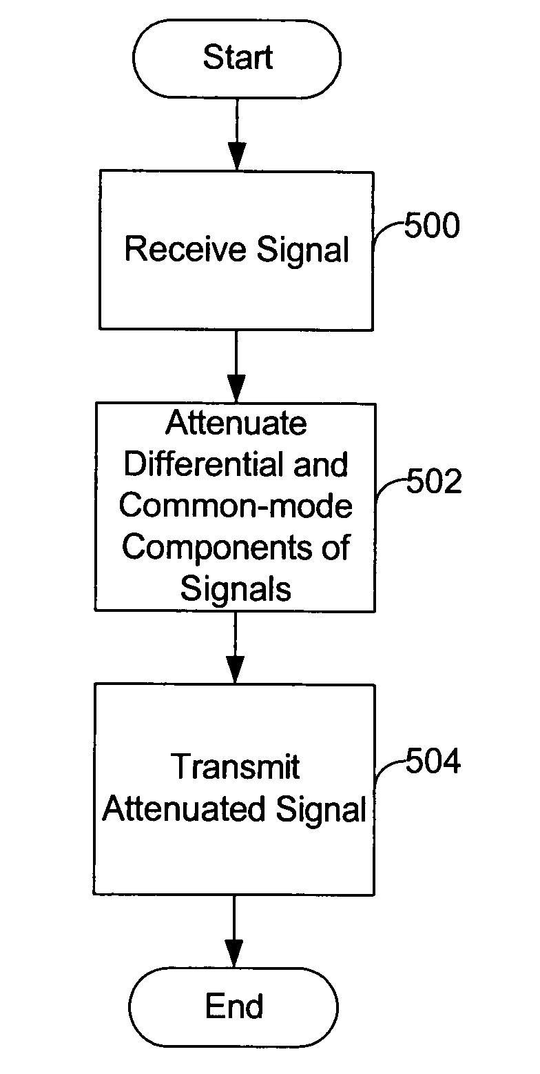
[0016]Embodiments of the present disclosure generally pertain to a cable simulator for simulating a transmission line. In simulating the transmission line, the simulator simulates attenuation of both differential-mode and common-mode components present in a signal passing through the cable simulator.

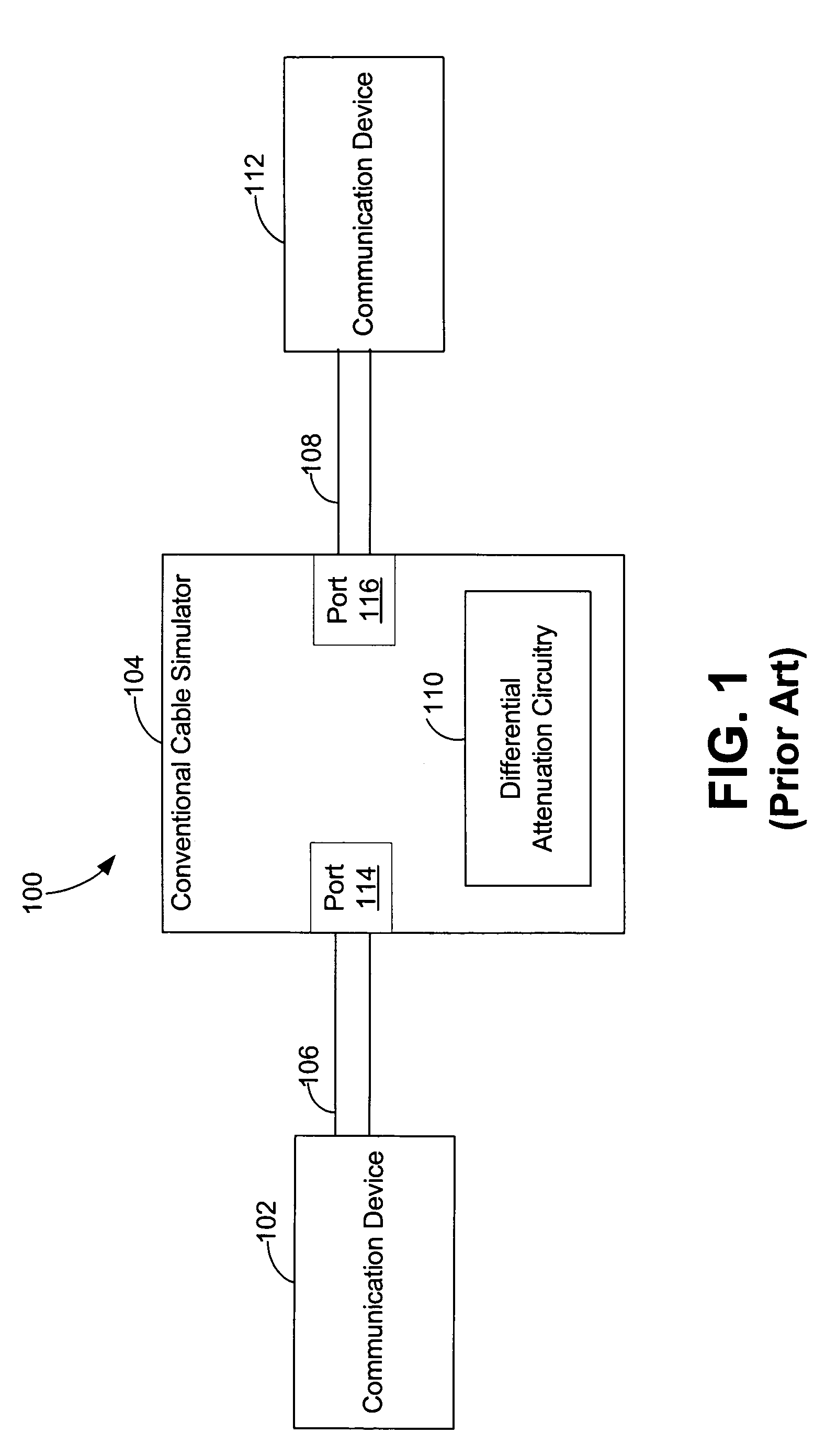
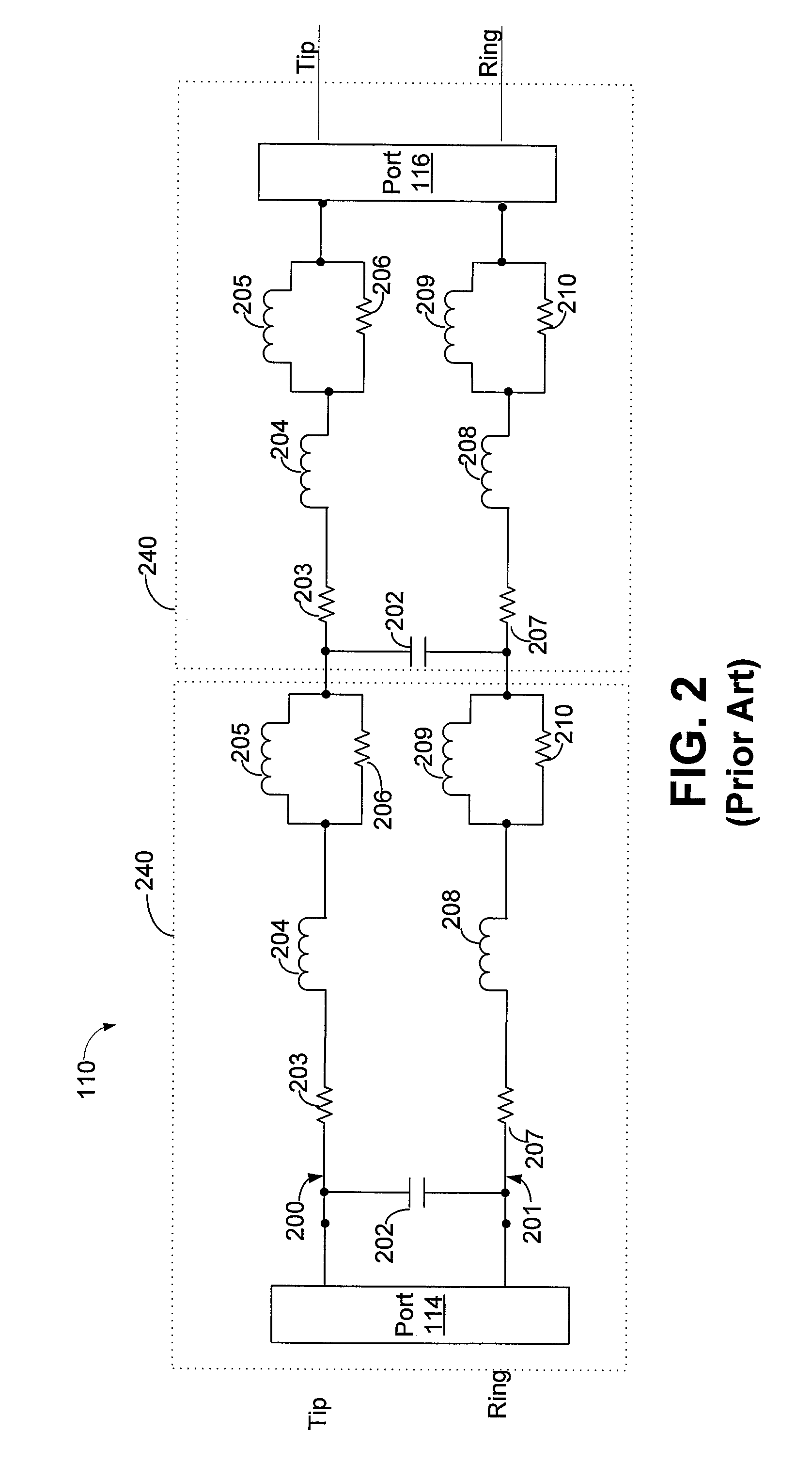
[0017]FIG. 1 depicts a communication system 100 that utilizes a conventional cable simulator 104 having only differential attenuation. The system 100 comprises a cable simulator 104 that connects a first communication device 102 at a first port 114 to a second communication device 112 at a second port 116. Cable 106, typically a length of several feet, connects communication device 102 to the cable simulator 104 at port 114, and cable 108 connects communication device 112 to the cable simulator 104 at port 116. The cable simulator 104 further comprises differential attenuation circuitry 110 that provides differential attenuation to the signal communicated between devices 102 and 112.

[001...


PUM


Abstract

A cable simulator that comprises an input device configured to receive a communication signal. The cable simulator further comprises a circuit configured to simulate attenuation in both the differential mode and common mode components of a communication signal.

Description

RELATED ART[0001]Data communication systems employ various transmission schemes in order to transmit data from one communication device to another. One such data transmission scheme is differential data transmission. In differential data transmission, a transmitter transmits a signal on two signal lines, sometimes referred to as “tip” and “ring,” and the difference between voltage levels of tip and ring forms the transmitted signal.[0002]In addition to the differential voltage applied to the signal lines, the transmitter typically transmits a common-mode voltage that is common to both signal lines. In this regard, the differential voltage across the signal lines is the desired signal, and the common voltage signal is an unwanted signal that may have been coupled into the transmission line by a driver of the transmitter. A receiver that receives a signal having both differential and common-mode components typically rejects the common-mode component of the signal in order to obtain th...

Claims


Application Information

Patent Timeline
Patent Type & Authority Patents(United States)
IPC IPC(8): G06F17/50
CPCH04B3/40
Inventor JOFFE, DANIEL M.
Owner ADTRAN
Why Eureka
Try Eureka