
Joint cover in aircraft

a joint cover and aircraft technology, applied in the field of aircraft joint covers, can solve the problems of affecting the service life of the aircraft, the gap or the joint dimension in relation, the panel deformation or displacement, and the visual change of the gap or the joint dimension, etc., to prevent the intrusion of objects, the joint cover may be easily and quickly mounted in the joint, and the effect of simple and secure joint cover

Inactive Publication Date: 2009-01-20
AIRBUS OPERATIONS GMBH
View PDF30 Cites 29 Cited by
  • Summary
  • Abstract
  • Description
  • Claims
  • Application Information

AI Technical Summary

Benefits of technology

The joint cover described in this patent is a protective cover for joints in an aircraft that can be easily and securely installed. The cover is made up of a clamp section and a cover section that can cover the joint. The cover is designed to visually and mechanically shield the joint from deformation and to prevent objects from entering the joint. The cover can be easily mounted on multiple surfaces in the aircraft and can include additional components like illumination, sensor, loudspeakers, and display devices. The joint cover is also designed to be cost-effective and flexible, with options for different materials and surface appearances. Overall, the joint cover provides a simple and secure solution for covering joints in aircraft interiors.

Problems solved by technology

Therefore, sometimes significant tensions act on the attachments or panel elements, which result in deformation or displacement of the panels and in visual changes of the gap or joint dimensions in relation to one another.
Elastic visual covers within or behind the joints, such as weatherstripping (“Kederbänder”), routinely malfunction during daily operation and require regular repair.
Furthermore, the required removal, installation, maintenance, and repair of the window panels or window front plates are time-consuming and costly factors in daily operation.

Method used


Image

  • Joint cover in aircraft
  • Joint cover in aircraft
  • Joint cover in aircraft

Examples


Embodiment Construction

[0035]The examples described and the drawings rendered are illustrative and are not to be read as limiting the scope of the invention as it is defined by the appended claims.

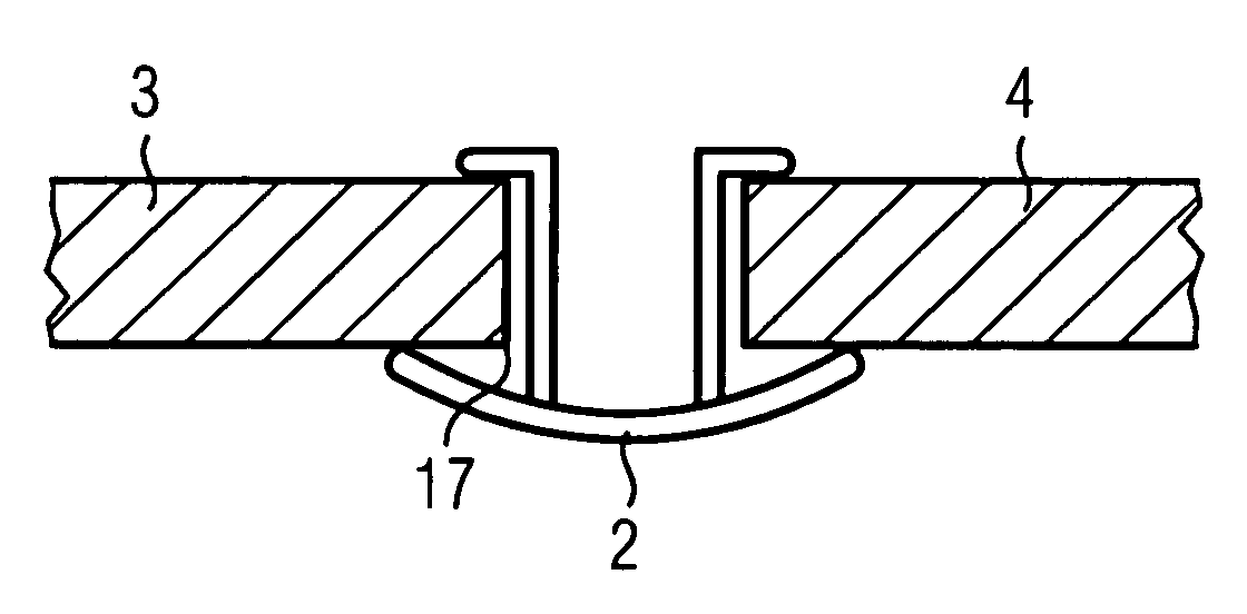
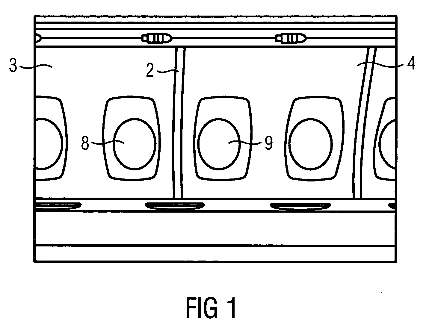
[0036]FIG. 1 shows a schematic illustration of a window area in an aircraft cabin. In this example, the window area has different wall panels or window panels or window front plates 3, 4 which receive the windows 8, 9. Wall panels, window panels and window front plate are examples of interior finishings. Because of the deformation of the aircraft fuselage during flight, such as occurs when pressure differences between the inside and the outside of the fuselage increase as an aircraft ascends to a cruising altitude, deformation and relative displacement of the window panels 3, 4 in relation to one another and the other panels may occur, for example. For this reason, the side panels 3, 4 are fixed at a distance to one another on the primary structure of the aircraft or other supporting parts. The joint lying betwe...


PUM


Abstract

A joint cover in an aircraft has a clamp section and a cover section for covering a joint. The clamp section is used to mount the cover section over the joint. The joint cover conceals the joint and secures the joint from intrusion of foreign objects. One example presents information to passengers, incorporating visual displays or other devices within the cover section. For example, the joint cover may include a cover section and a clamp section of an elastic material that deforms under pressure, concealing the joint even during compression and decompression of the aircraft, which causes movement of the panels defining the joint.

Description

RELATED APPLICATIONS[0001]This application claims the benefit of the filing date of German Patent Application No. 10 2004 049 893 filed Oct. 13, 2004 and claims the benefit of the filing date of U.S. Provisional Patent Application No. 60 / 618,130 filed Oct. 13, 2004, the disclosure of which is hereby incorporated by reference herein.FIELD OF THE INVENTION[0002]The field is aircraft joint covers, which are used to cover joints of a structure in an aircraft.BACKGROUND OF THE INVENTION[0003]In aircraft, interior furnishings, such as ceiling or wall panels, are attached to the primary structure or other supporting aircraft elements using appropriately mounted holder or attachment elements. The fuselage of the aircraft deforms significantly during flight, because of pressure differences, for example. Therefore, sometimes significant tensions act on the attachments or panel elements, which result in deformation or displacement of the panels and in visual changes of the gap or joint dimensi...

Claims


Application Information

Patent Timeline
Patent Type & Authority Patents(United States)
IPC IPC(8): B64C1/06
CPCB60R13/02B60R13/06B61D17/18B64C1/066B64D11/00B64C2027/8236B64D2011/0038
Inventor GRANZEIER, WERNERWIETZKE, ANDREASSCHROEDER, JAN
Owner AIRBUS OPERATIONS GMBH
Features
  • Generate Ideas
  • Intellectual Property
  • Life Sciences
  • Materials
  • Tech Scout
  • Unparalleled Data Quality
  • Higher Quality Content
  • 60% Fewer Hallucinations
Learn More