Vehicle bumper assembly

a technology for vehicle bumpers and components, applied in the direction of bumpers, vehicle components, vehicular safety arrangments, etc., can solve the problems of easy dent or deformation of fascia, vehicle components located behind and the lateral side ends of the vehicle bumper assembly are unsupported, so as to improve the resistance to damage

Inactive Publication Date: 2009-01-20
NISSAN MOTOR CO LTD
View PDF21 Cites 37 Cited by
  • Summary
  • Abstract
  • Description
  • Claims
  • Application Information

AI Technical Summary

Benefits of technology

[0006]It has been discovered that to improve resistance to damage at lateral side ends of a vehicle bumper assembly, the lateral side ends of the vehicle bumper assembly perform better with reinforcement behind the lateral side ends.
[0007]One object of the present invention is to improve the resistance to damage of the lateral side ends of the vehicle bumper assembly during low speed impact events. In accordance with one aspect of the present invention, a vehicle bumper assembly includes a bumper reinforcement member, a corner bracket and a biasing member. The bumper reinforcement member has a first lateral end section, a second lateral end section, an outboard facing side extending between the first and second lateral end sections and an inboard facing side with a vehicle mounting structure. The corner bracket is pivotally supported to the first lateral end section of the bumper reinforcement member proximate the inboard facing side. The biasing member extends between the outboard facing side of the bumper reinforcement member and an outboard side of the corner bracket. The biasing member biases the corner bracket outwardly relative to the vehicle mounting structure to a normal rest position for absorption of low speed impact energy.

Problems solved by technology

As a result, the fascia is unsupported at the lateral side ends of the vehicle bumper assembly.
Hence, when there is a low speed impact event with contact at either of the lateral side ends of the vehicle bumper assembly, the fascia is easily dented or deformed as a result of the impact event.
Further any vehicle component located behind the lateral side ends of the vehicle bumper assembly is vulnerable to damage as a result of the impact event.

Method used


Image

  • Vehicle bumper assembly
  • Vehicle bumper assembly
  • Vehicle bumper assembly

Examples


Embodiment Construction

[0019]Selected embodiments of the present invention will now be explained with reference to the drawings. It will be apparent to those skilled in the art from this disclosure that the following descriptions of the embodiments of the present invention are provided for illustration only and not for the purpose of limiting the invention as defined by the appended claims and their equivalents.

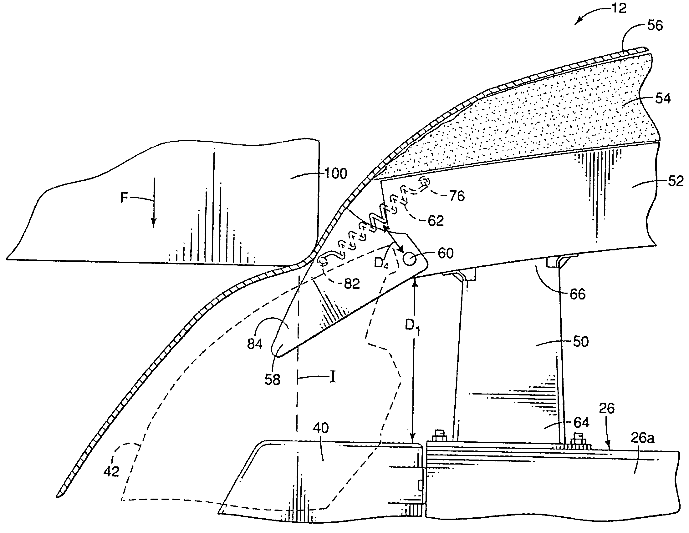
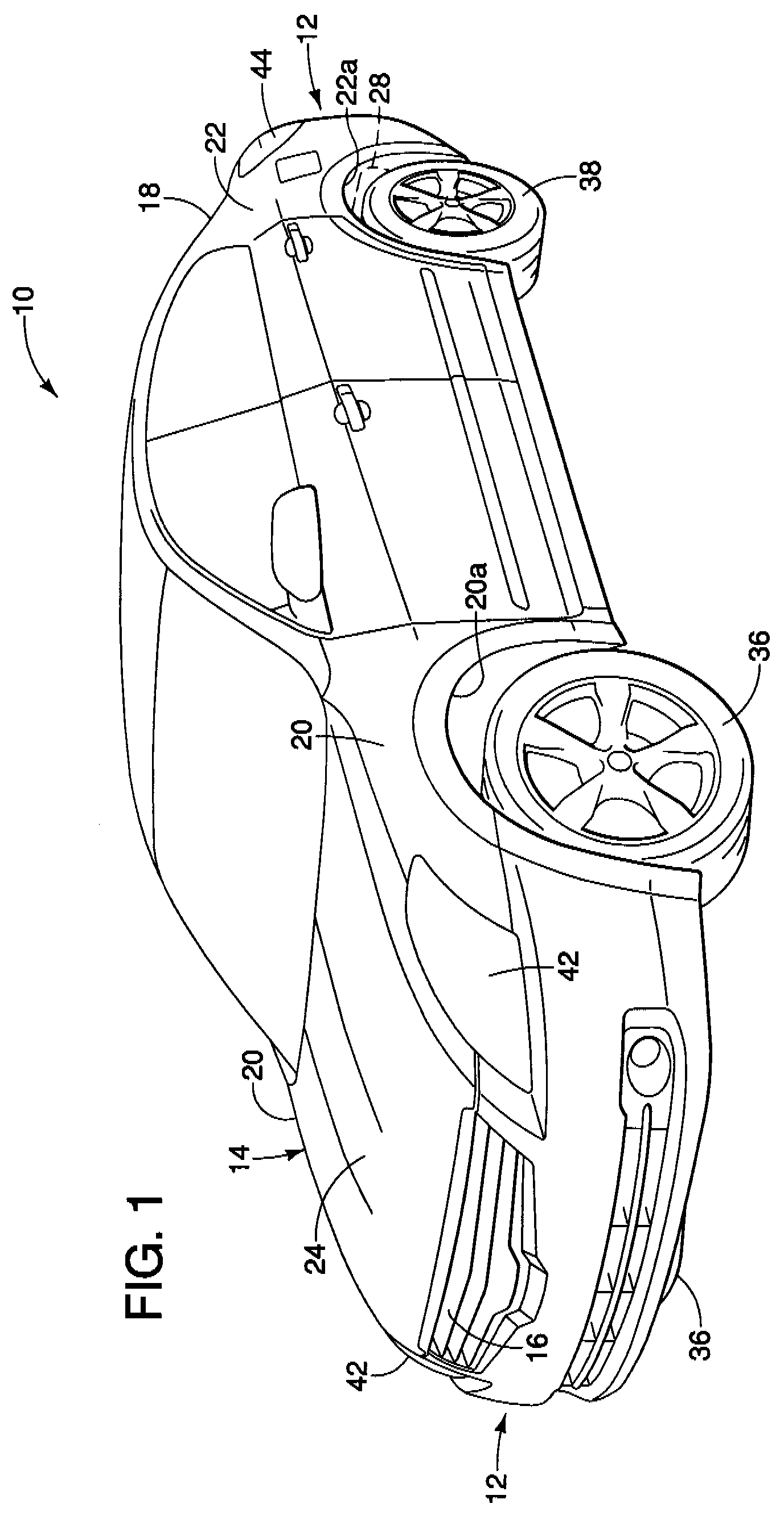
[0020]Referring initially to FIG. 1, a vehicle 10 having a bumper assembly 12 that provides lateral side ends of the bumper assembly 12 with resilience and resistance to damage resulting from low speed impact events is illustrated in accordance with a first embodiment of the present invention.

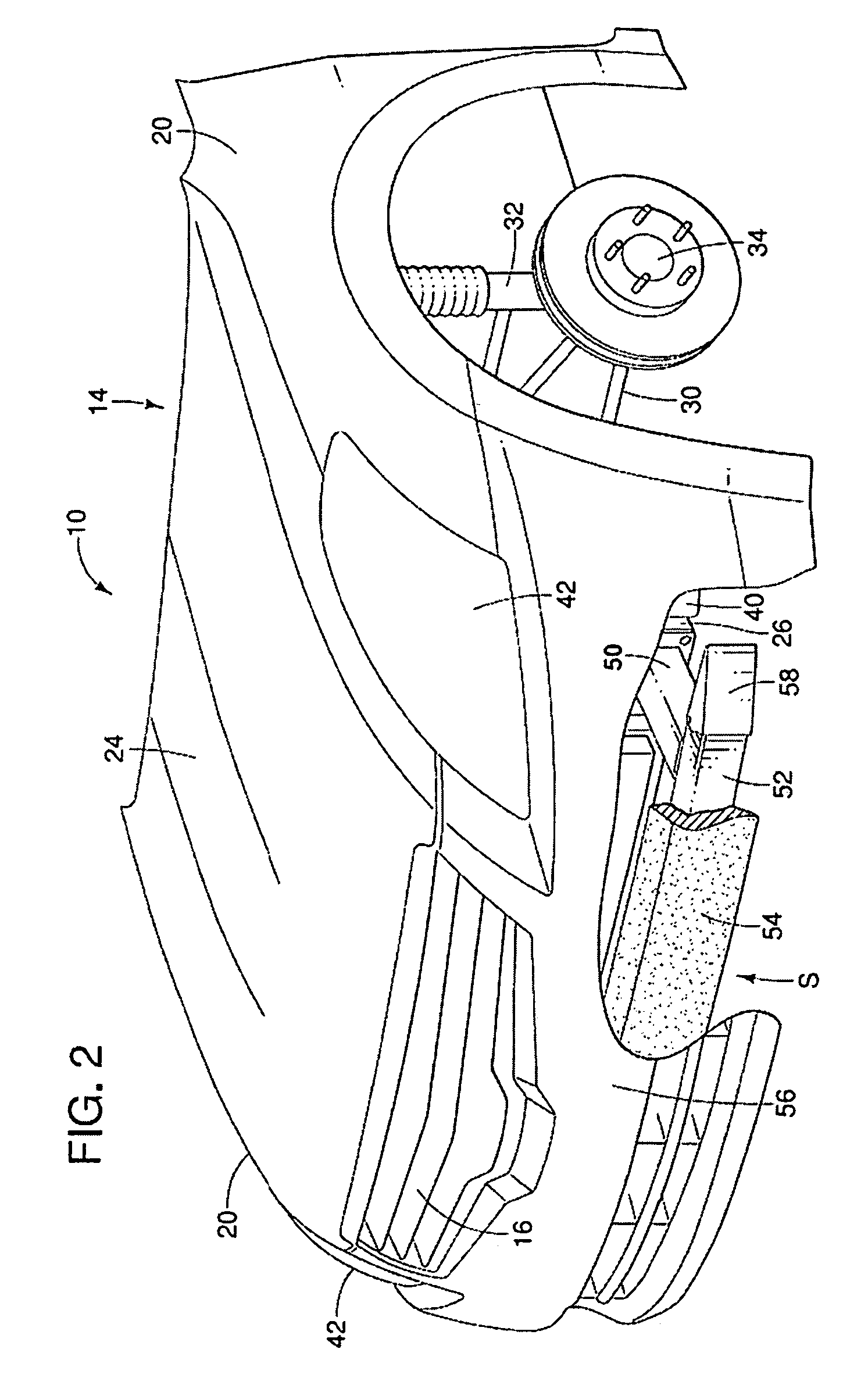
[0021]As shown in FIGS. 1 and 2, the vehicle 10 includes a vehicle body structure 14. The vehicle body structure 14 includes (among other things) a front end 16, a rear end 18, front fenders 20, rear fenders 22 (only one shown in FIG. 1), an engine hood 24, a forward end structure 26 (FIGS. 2, 3 and 6-9), a re...


PUM


Abstract

A vehicle bumper assembly includes a bumper reinforcement member, a corner bracket and a biasing member. The bumper reinforcement member has a first lateral end section, a second lateral end section, an outboard facing side extending between the first and second lateral end sections and an inboard facing side with a vehicle mounting structure. The corner bracket is pivotally supported to the first lateral end section of the bumper reinforcement member proximate the inboard facing side. The biasing member extends between the outboard facing side of the bumper reinforcement member and an outboard side of the corner bracket. The biasing member biases the corner bracket outwardly relative to the vehicle mounting structure to a normal rest position for absorption of low speed impact energy.

Description

BACKGROUND OF THE INVENTION[0001]1. Field of the Invention[0002]The present invention relates to vehicle bumper assembly. More specifically, the present invention relates to vehicle bumper assembly that includes resilient corner support structure.[0003]2. Background Information[0004]Vehicle bumper assemblies are continually being improved to resist damage during low speed impact events. A typical vehicle bumper assembly usually includes a rigid reinforcement member, an energy absorbing member and a fascia. The rigid reinforcement member is typically rigidly fixed to the vehicle body structure. The energy absorbing member is typically a resilient member that is fixed to an outboard side of the rigid reinforcement member. The fascia typically is a flexible molded member that conceals both the energy absorbing member and the rigid reinforcement member. The fascia also typically extends well beyond the side or lateral side ends of the energy absorbing member and the rigid reinforcement ...

Claims


Application Information

Patent Timeline
Patent Type & Authority Patents(United States)
IPC IPC(8): B60R19/02
CPCB60R19/18B60R19/14
Inventor FORTIN, HUGO F.
Owner NISSAN MOTOR CO LTD
Why Eureka
Try Eureka