Scanner

a laser radar and scanner technology, applied in the field of scanners, can solve the problems of relatively high production cost, malfunction of laser radar devices, and disadvantages of known state of the art, and achieve the effects of less sensitive, improved temperature compensation, and less sensitivity

Inactive Publication Date: 2009-01-20
SICK AG
View PDF12 Cites 30 Cited by
  • Summary
  • Abstract
  • Description
  • Claims
  • Application Information

AI Technical Summary

Benefits of technology

[0010]An advantage of the present invention is that the detection sensitivity along the path of the main stream can be adjusted in dependence on the light intensity of the sensing beam received by the light receiving element. With the reflection measurement from the sensing beam, the actual detection sensitivity of the main beam can be adjusted so that the amount of light of the main beam reflected by the object and received by the light receiving element for the main beam is within an optimal operating range for the light receiving arrangement. A particular advantage of the laser radar device of the present invention is that the sensing beam and main beam establish parallel operating measurement systems. This provides advance notice of the anticipated reflection for the main beam without reducing the responsiveness of the laser radar device.
[0011]In a preferred embodiment of the invention, the detection sensitivity for the path of the main beam can be adjusted by appropriately varying a switching threshold and / or an amplification factor in the electrical evaluation unit of the light receiving arrangement that is associated with the main beam. By adjusting the anticipated reflection values to the detection sensitivity of the laser radar device, it becomes possible to render the device less sensitive to interfering influences caused, for example, by other light sources.
[0012]In another advantageous embodiment of the invention, the voltage of an APD (avalanche photo diode) in the light receiving arrangement for the main beam is adjusted depending on the strength of the signal received by the light receiving element associated with the sensing beam. This reduces the influence of stray light and the like on the laser radar device. It further provides improved temperature compensation for the APD. This also improves the measurement accuracy in the case of high reflection values because the subsequent electrical evaluation unit will be less overloaded.
[0013]In a further embodiment of the present invention, an electrical control for the pulsed laser is adapted to adjust the initial energy of the emitted light pulses as a function of the signal strength previously determined with the sensing beam. By conforming the energy of the pulsed laser to the prevailing conditions, its output energy is kept at a level no greater than necessary. This significantly lengthens the life span of the pulsed laser.
[0014]In accordance with another feature of the present invention, the optical beam splitter associated with the light diverter of the laser radar device is arranged so that only a very small portion of the energy of the light pulses from the pulsed laser is fed to the sensing beam. According to a preferred embodiment of the present invention, the sensing beam receives only about 1% of the pulse energy emitted by the pulsed laser so that the strength of the main beam is only very slightly reduced. In other words, the reduction of the sensitivity of the laser radar device is practically unaffected by the formation of the separate sensing beam.
[0015]In a particularly preferred embodiment of the invention, the angular separation between the advanced sensing beam and the trailing main beam is exactly the same as the angular separation between two successive light pulses of the main beam. In this manner, it is assured that the light impulses of the trailing main beam proceed in exactly the same direction as the light impulses of the preceding sensing beam. This assures an optimal prediction of the anticipated reflection for the main beam because both the sensing beam and the main beam will strike a detected object at the same location on the object.

Problems solved by technology

A disadvantage of the known state of the art is encountered when such laser radar devices monitor large monitoring regions to detect objects with widely differing reflection characteristics.
Such a high signal dynamic leads to relatively high production costs.
It can also lead to a malfunctioning of the laser radar device.
Reasons for such malfunctioning can for example be external interfering light sources which are in the immediate vicinity of the monitoring region so that stray light from them can affect the light receiving arrangement of the laser radar device.
This can significantly interfere with the light receiving arrangement, the detection sensitivity of which must be set for the lowest expected signals received from dark objects in the monitoring region, because such interfering light sources generate significant amounts of stray light or background noise that becomes superimposed onto the measurement signal.
The same problem is encountered when light pulses emitted by the laser radar device are reflected by an object that has a high reflectivity and is located in the immediate vicinity of the laser radar device.
The high energy received signals cause saturation effects or noise interference which can significantly degrade the accuracy of the distance measurement.
It is also known to repeat inaccurate measurements by changing the detection sensitivity of the light receiving arrangement.
However, this approach is not usable with laser radar devices that change direction of the emitted light because successive light pulses involve changes in the beam directions so that different objects or object portions which are unrelated to each other would provide incompatible outputs.
However, this is not feasible because the responsiveness of the laser radar device would correspondingly decrease.

Method used


Image

  • Scanner
  • Scanner

Examples


Embodiment Construction

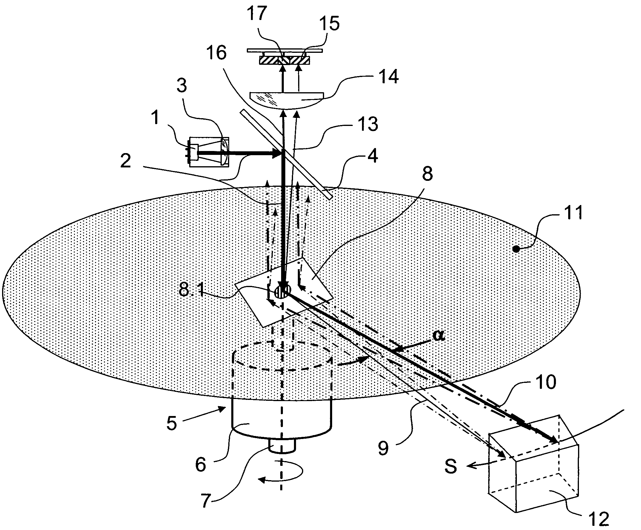
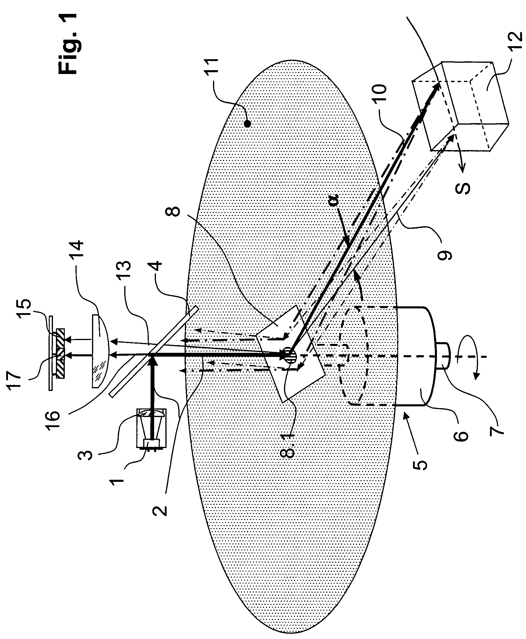
[0019]Pulsed laser 1 emits a light beam 2 in the form of successive light pulses. To affect the light beam characteristics, a projecting objective 3 is provided. After the light beam leaves projecting objective 3, light beam 2 is diverted by a partial mirror 4 which is aligned with the axis of rotation of a light diverter 5. FIG. 1 illustrates that light diverter 5 has a motor 6, which has a motor shaft 7, and a rotating mirror 8 that rotates about the axis of shaft 7 and is inclined by an angle of 45°. A beam splitter in the form of a diffraction screen or grating 8.1 is coupled to rotating mirror 8. The diffraction screen is preferably fitted to the cross-section of light beam 2. The diffraction screen divides the light beam that was deflected 90° by rotating mirror 8 into two partial beams, namely a sensing beam 9 and a main beam 10. Diffraction screen 8.1 is dimensioned so that the predominant energy of light beam 2 establishes the main beam 10. Only a small proportion of the be...


PUM


Abstract

A laser radar device that operates on an elapsed time basis and has a pulsating laser for emitting successive light pulses into a monitored region. A light receiver receives light impulses reflected by an object in the monitored region and generates electrical signals responsive to the received light impulses. The signals are forwarded to an evaluation unit adapted to generate a distance signal indicative of a distance between the object and the laser radar device on the basis of the speed of light and an elapsed time between the emission of the light pulses and the receipt of the reflected light pulses. A light diverter located between the laser and the monitored region continuously varies the directionality of the light impulses directed into the monitored region and includes a beam splitter that divides the energy of the emitted light pulses into a main beam and a sensing beam. The beam splitter causes a constant angular offset between the main beam and the sensing beam in the direction in which the directionality of the light beams is varied. A further light receiver is provided for receiving light impulses from the sensing beam reflected by the object.

Description

RELATED APPLICATIONS[0001]This application is based on and claims the priority of German patent application 102006027063.0 filed Jun. 10, 2006, which is incorporated herein by reference.BACKGROUND OF THE INVENTION[0002]This invention relates to a laser radar device that operates on an elapsed time basis and has a pulsating laser for emitting successive light pulses into a monitored region, a light receiving arrangement for receiving light impulses reflected by an object in the monitored region, and an evaluation unit that generates a distance signal indicative of a distance between the object and the laser radar device.[0003]Such laser radar devices are known from German patent document DE 43 40 756 A1. The laser radar device disclosed therein has a pulsed laser which directs successive light pulses into a monitoring region. A light receiving arrangement detects light pulses that are reflected by an object located in the monitoring region and sends corresponding electrical signals t...

Claims


Application Information

Patent Timeline
Patent Type & Authority Patents(United States)
IPC IPC(8): G01C3/08G02B26/08
CPCG01S7/4811G01S7/489G01S7/497G01S17/42
Inventor MACK, STEFAN
Owner SICK AG
Why Eureka
Try Eureka