Load transfer plate for in situ concrete slabs

a technology of in situ concrete and transfer plate, which is applied in the direction of resiliently-mounted floors, walls, and ways, etc., can solve the problems of reducing the life span of concrete, random cracks, and undesired addition of costs

Active Publication Date: 2009-01-27
ILLINOIS TOOL WORKS INC
View PDF97 Cites 48 Cited by
  • Summary
  • Abstract
  • Description
  • Claims
  • Application Information

AI Technical Summary

Benefits of technology

[0017]The tapered shape of the tapered load plate advantageously accommodates differential shrinkage of cast-in-place concrete slabs. When adjacent slabs move away from each other, the narrow end of the tapered load plate moves out of the void that it created in the slab. As the tapered load plate retracts, it will occupy less space within the void in the slab thus allowing the slabs to move relative to one another in a direction parallel to the joint.
[0019]In accordance with an illustrative embodiment of the invention, a tapered load plate and an end cap, may be used to provide load transfer across an expansion joint. The tapered shape of the load plate will allow for misalignment. As either or both slabs expand and thereby cause the joint to close, the wide end of the tapered load plate moves farther into the end cap. This results in the allowance of an increasing amount of lateral movement between the slabs parallel to the joint 400 to the central and relatively wider portions of the tapered load plate occupying less space in the tapered void.

Problems solved by technology

These random cracks 102 are undesirable as they detract from the performance of the floor slab 100 and reduce its life span.
For instance, if the dowel bars 402 are misaligned 600 such that they are not oriented totally perpendicular to the joint, the dowel bars 402 can lock the joint 400 thereby undesirably restraining the joint from opening, which in turn may cause random cracks 102.
The clips 902, however, undesirably add to the expense associated with using dowel bars 900 having square and / or rectangular cross-sections.
This use of round-cross-section dowel bars, however, is associated with the misalignment drawback discussed above in connection with saw-cut control joints.
A load plate 1100 is not, however, ideally suited for use at saw-cut control joints.
As described above, this type of joint results from cracking induced by a saw cut in the upper surface of a concrete slab.
Under such circumstances, an undesirably large area of load plates 1100 may undesirably be removed from slabs on either or both sides of the joint thereby reducing the ability of the load plate 1100 to transfer loads between the slabs.

Method used


Image

  • Load transfer plate for in situ concrete slabs
  • Load transfer plate for in situ concrete slabs
  • Load transfer plate for in situ concrete slabs

Examples


Embodiment Construction

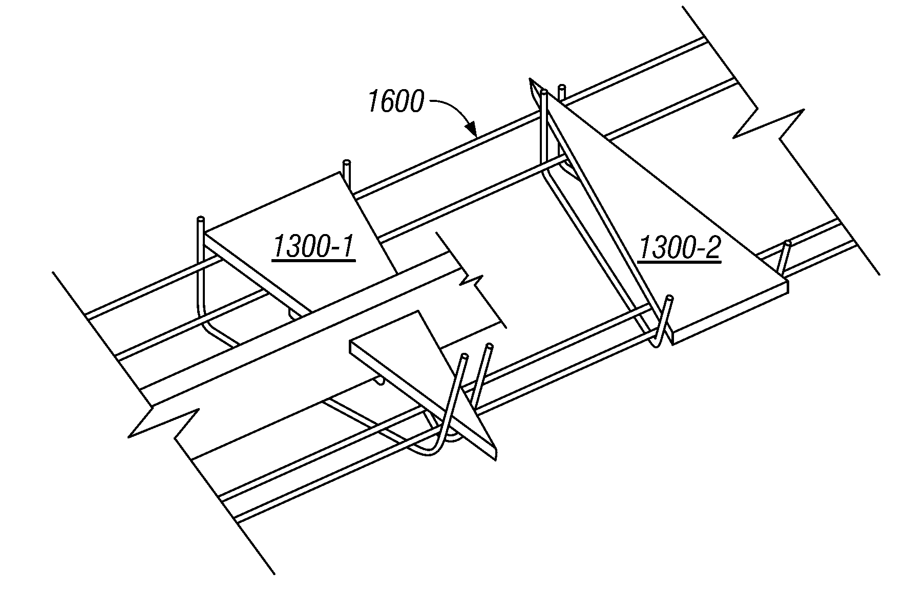
[0042]Referring to FIG. 13, in accordance with an illustrative embodiment of the invention, a tapered load plate, such as tapered load plate 1300, may be used to transfer loads across a joint between adjacent concrete floor slabs. The tapered load plate 1300 may have top and bottom surfaces that are tapered, substantially planar, and substantially parallel to one another. A triangular-shaped tapered top surface 1302 and two generally rectangular-shaped side surfaces 1304 and 1306 are shown in FIG. 13. The top and bottom surfaces may taper from approximately 4 inches wide to a narrow substantially pointed end 1308 over a length of approximately 12 inches. As will be apparent, other suitable tapered shapes and / or other suitable dimensions may also be used.

[0043]A tapered load plate 1300, in accordance with an illustrative embodiment of the invention, advantageously accommodates misalignment of a saw cut for creating a control joint. Misalignment up to an angle substantially equal to t...


PUM


Abstract

A tapered load plate transfers loads across a joint between adjacent concrete floor slabs. The top and bottom surfaces may taper from approximately 4 inches wide to a narrow substantially pointed end over a length of approximately 12 inches. The tapered load plate accommodates differential shrinkage of cast-in-place concrete slabs. When adjacent slabs move away from each other, the narrow end of the tapered load plate moves out of the void that it created in the slab thus allowing the slabs to move relative to one another in a direction parallel to the joint. Tapered load plates may be assembled into a load-plate basket with the direction of the taper alternating from one tapered load plate to the next to account for off-center saw cuts. A tapered load plate and an end cap may be used to provide load transfer across an expansion joint.

Description

[0001]This application claims priority to provisional U.S. Application Ser. No. 60 / 318,838, filed Sep. 13, 2001.TECHNICAL FIELD[0002]This invention relates generally to transferring loads between adjacent cast-in-place slabs and more particularly to a system for transferring, across a joint between a first slab and a second slab, a load applied to either slab.BACKGROUND OF THE INVENTION[0003]Referring to FIG. 1, when a concrete floor slab 100 is first placed and the concrete starts to cure the volume of the concrete decreases causing the slab to shrink (usually on the order of ⅛ of an inch per 20 feet). Concrete has a relatively low strength when in tension. When the internal stresses due to shrinkage 104 reach a point greater then the tensile strength of the concrete, random stress-relief cracks 102 occur.[0004]These random cracks 102 are undesirable as they detract from the performance of the floor slab 100 and reduce its life span. Referring to FIGS. 2A and 2B, a typical method o...

Claims


Application Information

Patent Timeline
Patent Type & Authority Patents(United States)
IPC IPC(8): E04B1/682E01C11/14
CPCE01C11/14
Inventor BOXALL, RUSSELLPARKES, NIGEL K.
Owner ILLINOIS TOOL WORKS INC
Why Eureka
Try Eureka