Coupling, particularly pipe coupling for high-pressure pipes or hoses

a technology for high-pressure pipes and couplings, applied in the field of coupling, can solve problems such as the follow-up of pipes or hoses

Inactive Publication Date: 2009-01-27
KARL HAMACHER
View PDF17 Cites 19 Cited by
  • Summary
  • Abstract
  • Description
  • Claims
  • Application Information

AI Technical Summary

Benefits of technology

[0008]It is an object of the invention to further develop a coupling, particularly a pipe coupling for high-pressure pipes or hoses, of the embodiment described initially, so that transport of the related pipeline or hose line, including coupling, succeeds in simpler manner than before and, in particular, without damage for the coupling.
[0011]The coupling pieces are disposed at a (slight) axial distance from one another and lie opposite one another in the region of a connection plane and / or abutment plane. As a result, the high-pressure pipes or high-pressure hoses, or pipes or hoses in general, make a transition into one another at practically the same diameter, even in the region of the coupling. Consequently, a pipeline or hose line having an almost continuously uniform outside diameter is available, even in the region of the coupling. This arrangement makes damage-free and simple transport of the pipeline or hose line possible, particularly in its axial direction.
[0013]In order to guide and hold the cuff in the interior of the coupling pieces without problems, the coupling pieces, taken together, have an accommodation for the cuff that is guided in them axially and radially. As soon as the cuff has been introduced between the coupling pieces and the coupling pieces have been displaced relative to one another, the cuff, in the accommodation, both functions as a stop and secures the position of the coupling pieces relative to one another at the desired axial distance, in the region of the abutment plane. In this way, it is guaranteed, at the same time, that related half-ring grooves in the cuff, on the one hand, and the related coupling piece, in each instance, on the other hand, taken together, form a ring groove for accommodating the related shear element.

Problems solved by technology

This use raises the problem that such pipes or hoses must follow the advancing shield structures.
In the past, problems have often resulted because the related pipe coupling projects beyond the outside diameter of the pipelines or hoses, and consequently can be damaged during transport, and / or no problem-free transport is possible.

Method used


Image

  • Coupling, particularly pipe coupling for high-pressure pipes or hoses
  • Coupling, particularly pipe coupling for high-pressure pipes or hoses
  • Coupling, particularly pipe coupling for high-pressure pipes or hoses

Examples


Embodiment Construction

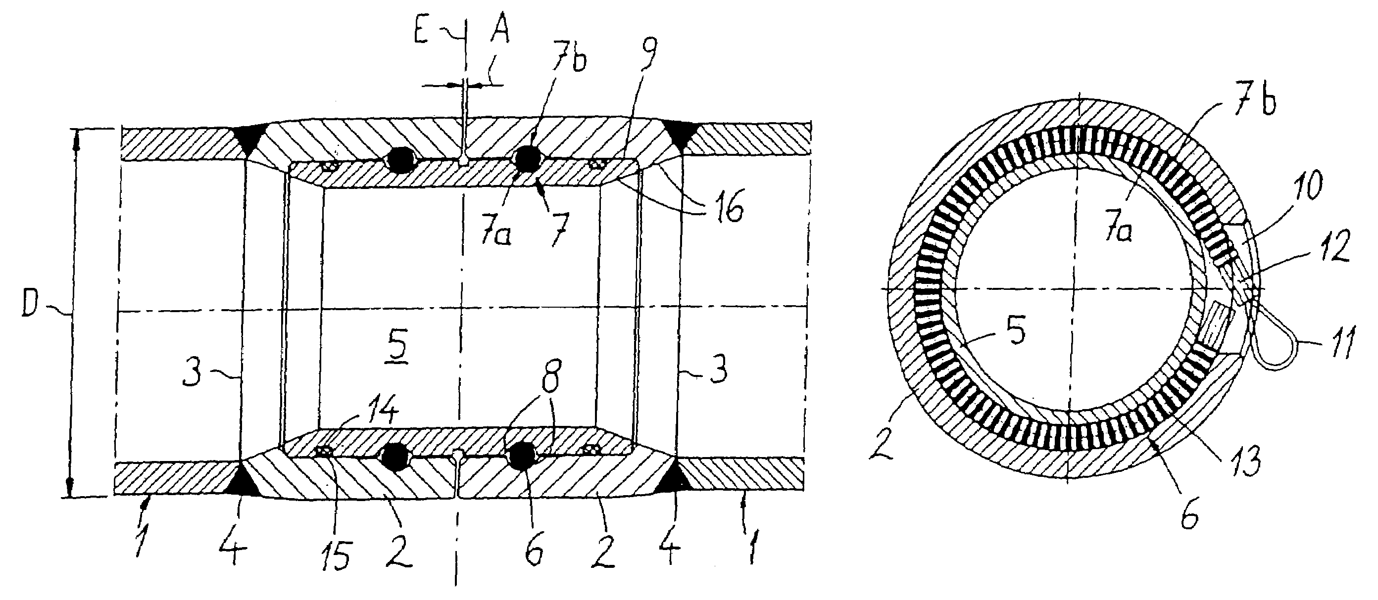
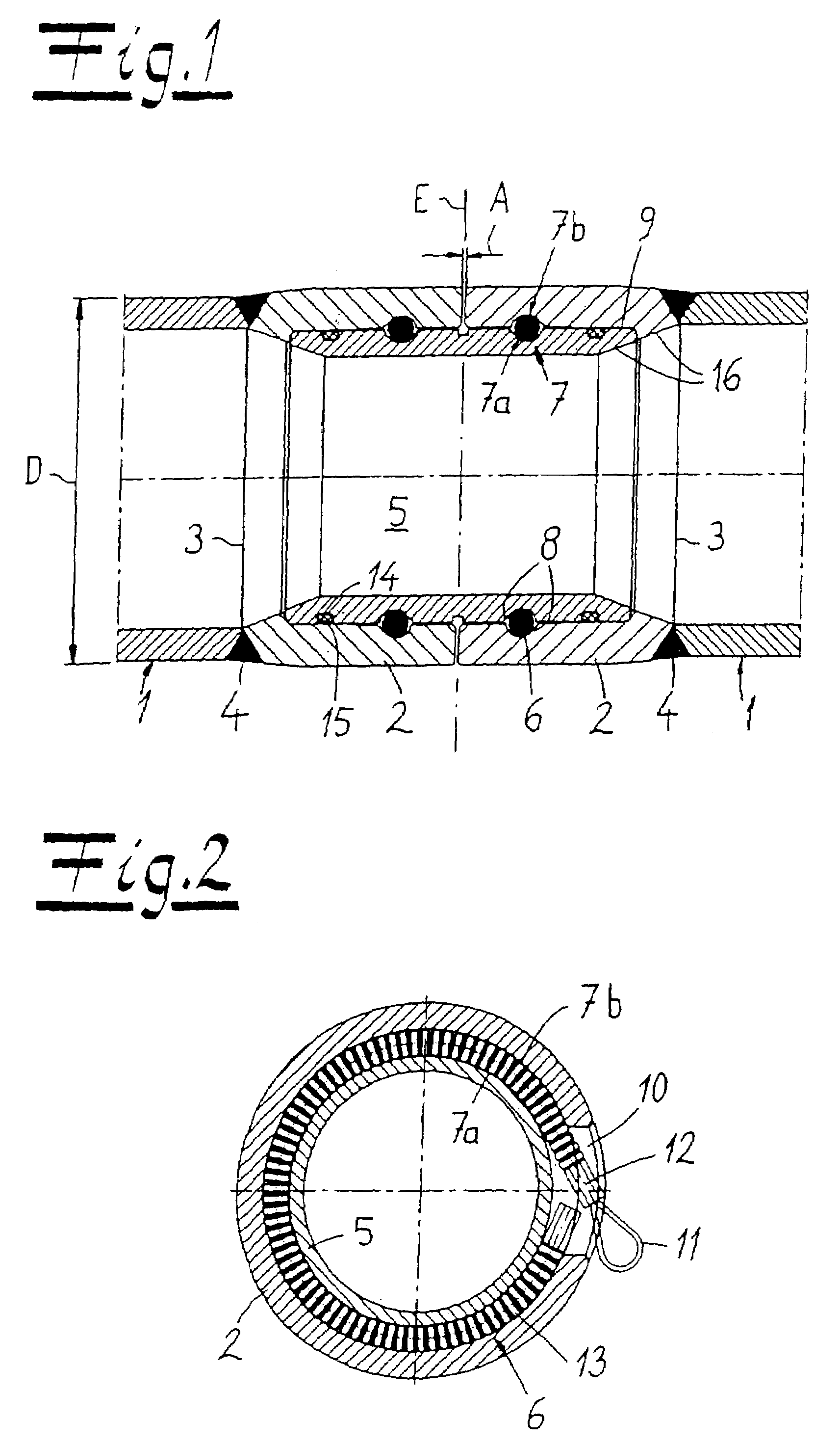
[0023]Turning now in detail to the drawings, FIG. 1 shows a coupling which, in the case of the exemplary embodiment, and without restrictions, is a pipe coupling for connecting high-pressure pipes 1. Of course, the coupling or pipe coupling could also be used for coupling hoses, not shown, or high-pressure hoses. In this connection, the hoses or the high-pressure pipes 1 and also the coupling are designed in such a manner that media can be transported in the interior, which possess a pressure far above 50 bar, particularly even several 100 bar pressure. The media in question are hydraulic media, which are used to supply tunneling machines in underground mining operations, as an example and without restrictions.

[0024]The coupling in question, which is configured with rotation symmetry and in cylindrical manner, without restrictions, is composed, in its fundamental structure, of two coupling pieces 2, which are provided on ends 3 of the high-pressure pipes 1 to be connected, in each i...


PUM


Abstract

A coupling, particularly a pipe coupling for high-pressure pipes or high-pressure hoses, is equipped with coupling pieces provided at the ends to be connected, in each instance, and with a cuff that couples the coupling pieces, using at least two shear elements. The coupling pieces engage over the cuff that lies on the inside, as an extension of the ends, with almost the same diameter.

Description

CROSS REFERENCE TO RELATED APPLICATIONS[0001]Applicant claims priority under 35 U.S.C. §119 of German Application No. 10 2006 027 015.0 filed Jun. 8, 2006 and European Application No. 06 015 775.7 filed Jul. 28, 2006.BACKGROUND OF THE INVENTION[0002]1. Field of the Invention[0003]The present invention relates to a coupling. More particularly, the invention relates to a pipe coupling for high-pressure pipes or hoses. The coupling has coupling pieces provided at the ends to be connected, in each instance, and has a cuff that couples the coupling pieces, using at least two shear elements.[0004]2. The Prior Art[0005]A coupling of the embodiment described initially has become known from the utility model DE 73 41 019 U1. This coupling is a connecting element for a pipe connection secured against shear. High-pressure pipes or high-pressure hoses, in other words pipes or hoses for the application of pressures above 50 bar, usually taking into consideration pressures up to several 100 bar, ...

Claims


Application Information

Patent Timeline
Patent Type & Authority Patents(United States)
IPC IPC(8): F16L37/00
CPCF16L3/18F16L37/148
Inventor FUSSER, BERND
Owner KARL HAMACHER
Why Eureka
Try Eureka